


(Complete list of all blog entries in this series)
So this was a longer break, but the skiing vacation was really needed. Since I could not take my ADXL375 with me (though it arrived 2 days before I left) I tried to have some measurements. I was especially interested in getting some data about accelerations that happen during normal (downhill) skiing, and maybe compare them with what happens when I would fall down.
So I looked through the apps that are available on Android for measuring acceleration, and installed some of them. After playing around a little bit I settled with using Acceleration Monitor. Its most important feature was to calculate an acceleration vector, and storing its maximum value for the app runtime. All programs where able to draw nice graphs of the acceleration axes, some could also calculate the absolute vector. But a graph for the past 60 seconds or so doesn't help me, I don't want to look constantly at the phone (especially not with -10°C outside...).
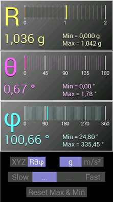
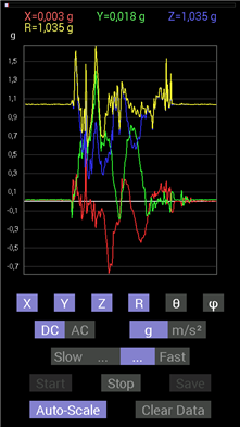
The app not only calculates the absolute vector value, but also its direction. If you need, it can also store a graph, but there is no scrolling for history data...
So what did it report? Well, the highest acceleration it measured during skiing was about 2.8g. If you subtract the normal earth acceleration this leaves just 1.8g, which is not so much. Unfortunately (for this exercise) my skiing skills have improved in the last few years, so I did not fell down so often - and when I did, I had the app not running (it really drains the battery since the phone and the display are always one).
But there is one interesting comparison to be made: I had the phone in the front pocket of my jacket. And when I had the app running while just walking around (taking the skis, hopping onto the ski lift and so on) it reported an acceleration of up to 2.5g. Go figure. Surely skiing felt much more taxing than just walking around...
Lets get this ADXL375 running
Back at home I started work on the real accelerometer. First I looked at the real time evaluation board, because I wanted to spare the breakout board for mounting on the PSoC4 BLE board. I liked the idea of using a LGA socket for mounting the chip, it allows playing around with different variants. The whole kit also makes a good first impression, its a solid build. But that where it ends.
I had a really hard time to come up with all the information I needed. There was a CD in the box with the kit, but it had no software for the ADXL375 on it (only for all the other accelerometers from Analog Devices). So I started looking at the Analog Devices web site, but its hard to find something under the part number of the kit (only the breakout board comes up). If you happen to find out that the thing is called "Real time eval system for digital sensor output" (with the short code EVAL-MST-ISEB) you have more luck (but with the web site redesign that happened just now even then nothing is to be found). So after a while I found the firmware that needs to be uploaded to the mother board of the kit, and did so successfully.
Next hurdle was to get the GUI for evaluation running. As first step the Labview runtime needs to be installed, and then the GUI itself. Having done both the GUI complained that it needed a "Labview 2010 compatible runtime" - the one on the CD was version 2007. Installing the Labview runtimes from the National Instruments website also did not help. In the end I found a forum post in the AD Engineer Zone that had a link to Analog Devices special version of the runtime, which finally did work.
All in all that took me two evenings just for installing stuff that should have been done in 5 minutes. There is room for improvement.
Documentation-wise its not much better. The CD has a schematic for the motherboard (which I think cannot be found anywhere else), and for the ADXL345 satellite board (and I need to assume that its the same board as for the 375). Since I wanted to re-use this board to connect it to the PSoC for my first experiments there, I looked at how the satellite works. Next hurdle: the documentation doesn't really match the schematic. According to the docs, the provided jumper configuration should connect all ADXL375 pins to the SPI lines on the connectors. But according to the schematic SDA is connected to the I2C pin SDA1A but should be on MOSI. There is also no documentation how these two boards work (there is a level shifter on the satellite, but the voltages its using are not documented). So I decided not to use it for the PSoC experiments, since I did not want to damage it.
Having jumped through all these hoops, the evaluation is actually quite nice. The GUI allows to play around with all the features the accelerometer has:
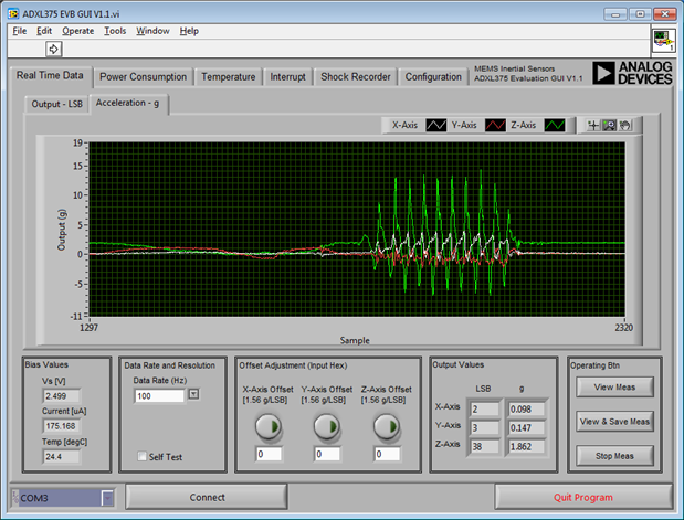
You can look at the acceleration values for each axis, set the data rate and even see the raw values.
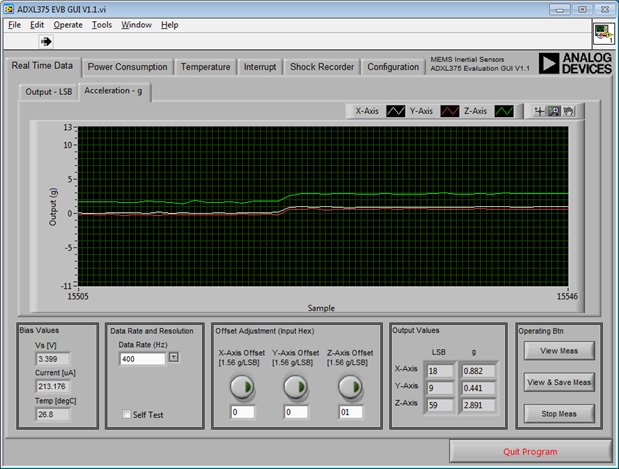
Since you can set the supply voltage (on the configuration tab), I played with it and discovered that the offset values for the acceleration depend heavily on the supply voltage. The jump here is by going from 2.7 up to 3.3V.
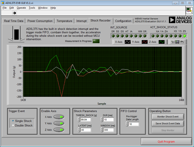
One can also configure and test the shock monitor. The values here are the recorded events. I also tested with the interrupts and their configuration, and played with the different data rates and their effects.
So after getting a feeling for how the ADXL375 behaves, and playing around with its feature its time to get down to the real business.
The ADXL375 and the PSoC4
First task: connections. Since the PSoC4 BLE board, equipped with the breakout, is too high to safely accommodate my Arduino LCD shield (the shield would touch the breakout board) I used by Pioneer board for the task. So I soldered wires to the breakout, and right-angle pin headers to the other side of the wires. Placement of the pins needed some careful consideration, since the fixed-function SPI component of the PSoC requires some dedicated pins. And not all of them are available on headers, and some are used by the LCD shield.
I finally settled for a pinout, and started going. The Hardware side is rather simple, one juts needs a handful of components:
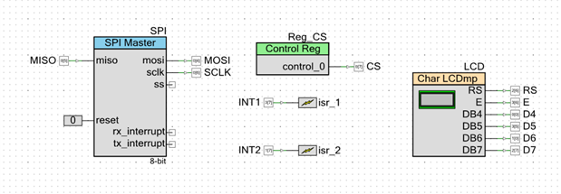
As already stated, I originally stated that I used the fixed-function SPI, but I later on changed that to the UDB-based version. I encountered a problem that might be a problem in the FF SPI component, so I wanted try the other one.
Its configuration also is simple enough:
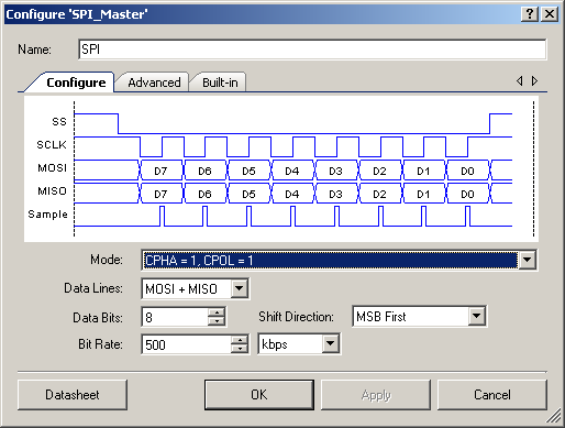
No need to fiddle with registers or doing bit-rate calculation, just state what you need.
The software side is simple too, there is a nice API with just read and write and it takes care of all the rest.
First step was to read the device ID to see whether I can get the communication working. The code for that is easy:
CyGlobalIntEnable; // enable global interrupts

// start the components
LCD_Start();
SPI_Start();

// make sure the ADXL is disabled
Reg_CS_Write(1);
CyDelay(10);

// start transaction
Reg_CS_Write(0);
CyDelayUs(5);
SPI_WriteTxData(0x80); // == read register 0
SPI_WriteTxData(0x00); // write dummy byte to read
Reg_CS_Write(1); // end transaction

SPI_ReadRxData(); // read dummy byte
uint32 id=SPI_ReadRxData(); // read ID

LCD_Position(1,0);
LCD_PrintString("id=");
LCD_PrintHexUint8((uint8)id);
Only problem: this won't work. It actually required that I used a scope to look at the SPI lines to see what happens (thanks to Tektronix for providing me with a TBS1202B-EDU, I appreciate that!). A logic analyzer would have been even better (and had solved that with a single glance). But looking at the signals ony by one revealed that the CS line goes to high even before the second clock pulse.
I should have known that: the SPI component uses a TX and RX FIFO, so the bytes to be send out are just placed there and then the function returns. So I need to wait for the SPI transfer to finish before pulling CS high again.
So I added this call too, and voila there was the ID (0xE5).
Next step was to read acceleration values. Trap for starters: the device powers up in power-save mode, so it doesn't to measurements at all. One needs to set it to normal mode to get any data. Doing so revealed data for all three axes:

I also calculated the absolute value of the acceleration value, since this is the final value I need. What I noticed is that there is a heavy offset. According to the data sheet the normal offset is 0.4g, but can be as high as 6g. My device shows for Z an offset of 1g, so if I put it upside down it shows 0g, but 2g in normal position. The x axis is also way off.
So I know that I need to handle the offset. The ADXL375 can do that in hardware, but a resolution of 1.56g per LSB is quite coarse. So I will do that in software, and trigger it via the phone app.
Next steps
So next on my list will be the offset handling, and the I can work more deeply with the FIFO handling. I want to put the PSoC to sleep between readings as much as possible, so the FIFO should do most of the work. Also, some value aggregation needs to be done, and the RRD handling must be implemented.
I found a supplier that has really small Li-Polymer batteries, so I ordered some of them. This should give me some more room in the enclosure, maybe I can even use a smaller one now. When the PSoC software side is done, I will move the code over to the PSoC4 BLE, and mount the accelerometer on the BLE breakout board. So stay tuned 