


Some of my ordered parts started to arrive, which made me happy and enthusiastic to start doing some work. My first experiment tried to make a radio link connection between a QAM-TX1 transmitter and a QAM-RX2 receiver. QAM-TX1 is a complete transmitter hybrid module that operates at 433MHz and it is specified to handle TTL/CMOS data up to 3kHz. The other module, QAM-RX2 is a complete RF receiver operating also at 433MHz and which provides TTL/CMOS output. Here is the radio link setup:
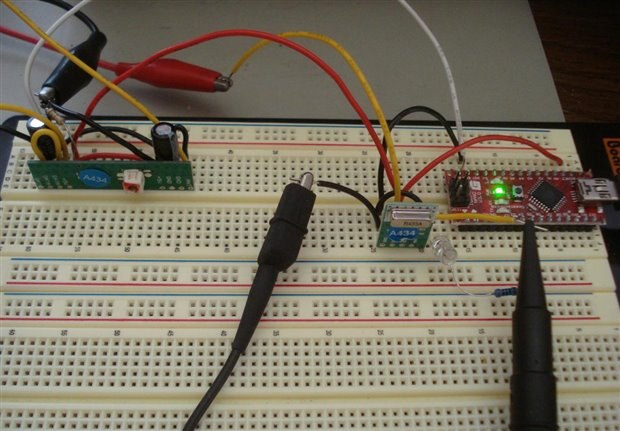
The transmitter is the small module on the right side, connected to the Arduino nano module, and the receiver is the board on the left side. I have setup a small program running in the Arduino processor to send pseudo random data to the transmitter. The sketch of that program is shown in the following screenshot:
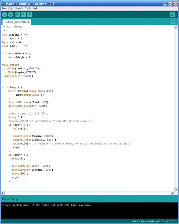
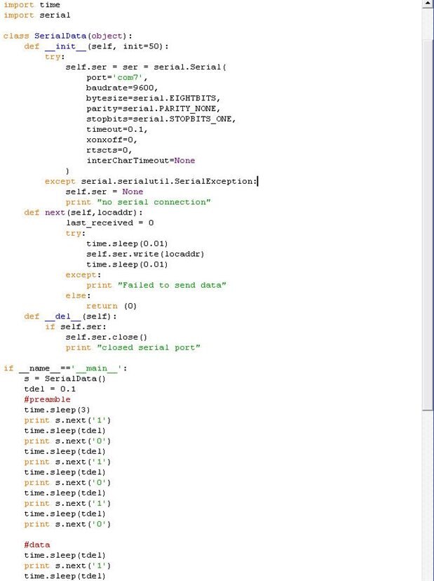
And the Python program that controls the data pattern is shown in the screenshot below:
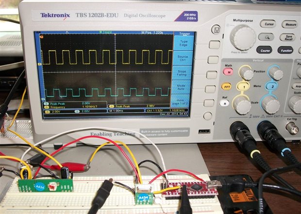
I then used the Tektronix TBS1202B-EDU oscilloscope to probe the input signal into the transmitter and the output signal of the receiver board, as I am showing in the following picture.
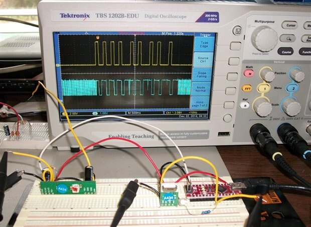
Channel 1 of the oscilloscope (yellow trace) probes the digital pattern generated by the Arduino processor and applied to the input of the transmitter, and channel 2 probes the output of the receiver.
First thing that I noticed is that before and after the data pattern there is a lot of noise at the receiver output (random pulses), and also during the data pattern there are three regions with glitches. These regions coincide with the three longer pulses in the pattern.
These results were not promising at all, so I continued with some characterization experiments of this RF transmission link. Next I disconnected the Arduino signal and I applied a square-wave signal from a pulse generator, as I am showing in the figure below::
The frequency was 1kHz, and the received signal followed the transmitted signal. I then increased the frequency to see where the transmission link breaks. The following picture shows the transmitted and received signals at 11kHz frequency.
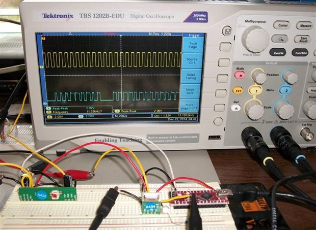
Notice how from time to time some of the received pulses are missing. Next step, lowering the transmitted frequency I came to the conclusion that at 6.5kHz there are no missing pulses, like I am showing in the picture below:
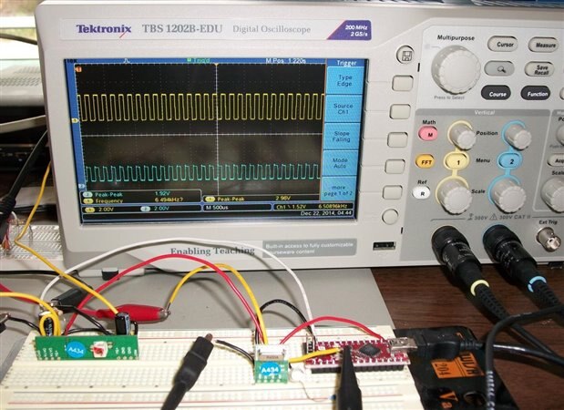
So this is the upper frequency limit for square-wave signal, but this does not mean that a random data pattern will transmit without error. The published highest frequency in the datasheet is 3kHz, so I am happy to see in this experiment that I’ve got it to work up to 6.5kHz.
Next I explored that lowest limit of the transmitted frequency, and here are the waveforms at 1.6Hz:
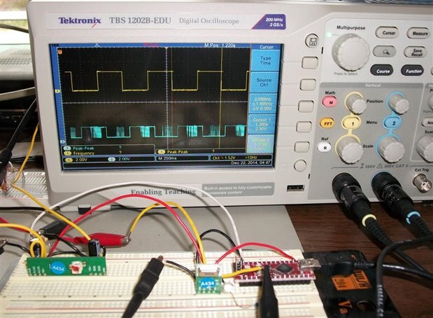
Notice the glitches that show up about 100ms after each rising and falling edges. I suspect that the origin of these glitches is a combination of 1/f noise and popcorn noise, which limits the functionality at lower frequencies.
So based on these experiments I think I can use this RF transmission link in my project if I am careful to limit the data rate within the functional bandwidth.
That is all for this update; I will come back with more info after I receive other components (and modules) and I complete more work on this project.
Until then all my best wishes and
Happy Holidays!
Cosmin
Top Comments