


After all the testing and prototyping of the project parts it is time to assemble them together. In this blog post I will quickly cover the components that we are using and assemble them all into a working prototype.
In this blog post I will cover the components we have not yet looked at and then assemble them into a breadboard prototype.
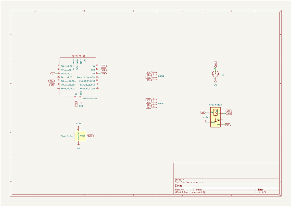
One thing to note is that the electronics for Cool Wave are intentionally and unapologetically simple. One of the driving factors of the Cool Wave design is for it to be used by, modified by and improved by non-engineers. Very much like the ethos behind the original Arduino design. I can not create a solution for every eventuality, but I can create something that can be modified by most people to fit their needs.
What has already been covered
In earlier the blog posts we looked at setting up the Seeeduino XIAO Arduino Microcontroller Board.
We also looked at many temperature sensors and decided to use a DHT12 and a DHT20.
Relay module and fan
For the project I have decided to recover an old PC fan. Any low voltage fan will work, but a generic computer is low power, low noise, and available second hand for low cost or free. Most of these fans will have three wires, one red, one black, and one yellow. Red and black are the power supply, normally 12v, and yellow is for monitoring the fan. We could use this to monitor the fan, but for the moment we are just going to leave it unconnected.
In the ethos of keeping things simple and accessible I have decided to use a simple relay module to turn on and off the fan. There are many types of module, but some will not work work with a 3.3v signal coming from the microcontroller, such as the Seeeduino XIAO. It is worth testing this before committing to one, but many will work.
Here is some test code I used to test the module. It is some simple blink code, but additionally toggles the data pin 2 (GPIO 10).
from machine import Pin, Timer

led = Pin(18, Pin.OUT)
relay = Pin(10, Pin.OUT)
Counter = 0

def switchit(timer1):
    global Counter
    Counter = Counter + 1
    led.value(Counter%2)
    relay.value(Counter%2)

timer1 = Timer(-1)
timer1.init(period=1000, mode=Timer.PERIODIC, callback=switchit)
As you can see it is working here.
Power Supply
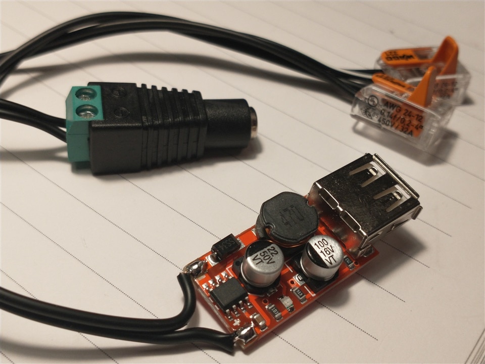
The main power will come from a “wall wart” that is the same voltage as required by the fan. In this case that is 12v. In the photograph is a female power connector to screw terminal adapter and these are a really useful thing to have lying around. I use them all the time and it is an easy way of extending a wall wart power supply cable.
The incoming power cable will terminate at some Wago connectors that will connect to the fan and a buck converter for the rest of the electronics.
Because of the drop in voltage from 12v to the 5v needed to power the rest of the electronics, a simple power regulator is not appropriate. More power will be wasted as heat than used. The good news is that a DC to DC buck converter (photographed) is low cost and efficient. We could use one that is soldered directly onto the microcontroller, but I have chosen to use a USB C cable to allow easy testing and reprogramming.
Putting it all together
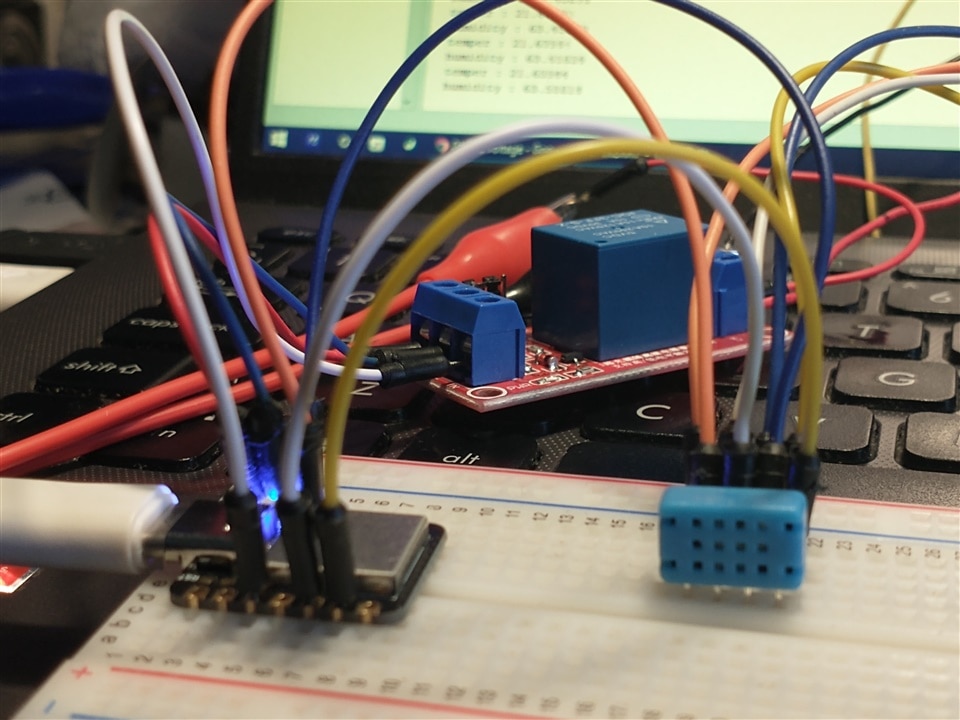
All this will be soldered together and later mounted in an appropriate enclosure, but for the moment I am going to use a breadboard to test everything together first. That said, if I exclusively use Seeed Studio Grove sensors then no soldering would be required.
I will go over the assembly in more detail in the next blog post when I do the physical and final build, but here is a video of the system working. I am testing with some early stage code and a hairdryer to apply heat.


