Recap
For those of you joining the show late, welcome aboard! For those of you returning for a 5th time, wow, thank you!
Just to recap, this is my fifth blog in the Summer of Sensors Design Challenge kindly sponsored by Element14 and in my case Vishay. The challenge was to design something incorporating a proximity sensor, an ambient light sensor and a colour sensor from Vishay’s SensorExplorer range of sensor boards. My idea is to create an adaptive, smart bulb controller. The basic concept is that the proximity sensor will be used to turn the smart bulb on or off when the user sits down or walks away from it respectively; the ambient light sensor will be used to adaptively control the brightness of the bulb to reduce eye tension much like the screen on a smartphone; the colour sensor might be used to set the hue of the bulb to match the room colour. If you are new here, then please catch up on the project progress in the previous blogs – there’s also a video blog (or should I say vlog these days) which is well worth a watch.
Introduction
In today’s blog we will be starting to integrate the Vishay sensors to my selected microcontroller – the ESP32.
When it comes to this stage of the project, there is a very useful aid required. Immediately your are probably thinking of an all-signing, all-dancing, 4-channel oscilloscope which automatically decodes I2C data. Well, that is a very useful tool and I may well be using that if we run into some problems, but that is not what I am referring to here. The most important thing you will need when integrating is the datasheet. Whether an electronics engineer designing the circuit, or an embedded software engineer writing the code, or a mechanical engineer designing the enclosure with suitable thermal characteristics, everyone needs to refer to the datasheet. Generally we don’t read the datasheet from cover to cover, we just use it as a reference guide to look up the bits that we need – for example I don’t care about the 20 pages telling me how big the pads are on the surface mount device (SMD) neither do I care about the amount of solder required to mount the component because Vishay have already created a working circuit for me and done the PCB layout. Instead, I am interested in how to power the device, how to interface to other devices, and how to control the device.
Today we will be:
- Finding the datasheets we require
- Filtering through the datasheets and extracting the important information we need
- Building a basic circuit to integrate the ESP32 to Vishay’s VEML3328 colour sensor board
- Write some code to control the RGB LED
- Write some code to read the colour sensor
- Test it
Powering the Sensor Board
The first bit of information I require is how to power the sensor board. Having performed a bit of research into this board, it turns out “VEML3328” is the name of the actual RGB sensor (not the whole board) so searching for a VEML3328 datasheet will not be sufficient. Instead I navigate to the Vishay website and go to the SensorExplorer landing page. From here I can find a link to the datasheet for their VEML3328 sensor board.

Scrolling down to page 3 of this datasheet we find exactly what we are looking for – a schematic for the sensor board itself.

After studying this schematic I have to make the following observations:
- There are two I2C devices on this board. One is the actual VEML3328 light sensor (top right), the other is a PCA9554 (top left) which is an I2C GPIO controller.
- Both of the I2C devices are powered from the 3v3 power rail.
- Both of the I2C devices are on the same I2C bus (so they will/should have different slave addresses).
- The RGB LED (middle right) is controlled by some MOSFETs connected to the PCA9554 device.
- The RGB LEDs are powered from the 5v power rail.
- There is a note about requiring to have external resistors on the I2C lines. However, the ESP has configurable pull-up resistors, so no external circuitry will be required at all – just wires connecting the power, ground, I2C data and I2C clock.
From a power connection point of view if we just want to use the colour sensor, then we will only need 3v3 power, but if we want to use the RGB LEDs then we will need 5v (to power the LEDs) as well as the 3v3 (to power the I2C devices) since the 3v3 is not generated from the 5v.
Since we will have the ESP32 connected to a USB for downloading firmware and debugging, we can sink the 5v and 3v3 power from the ESP32 for the VEML3328 sensor, so no external power supply will be needed. Now we need to find the pinout for the ESP32. I am using the ESP32-PICO-KIT, so navigating to their website I find a HW reference containing a handy table of pin descriptions:

Of most interest are those last three lines identifying the 5v, 3v3 and ground pins. After soldering some headers onto the VEML3328 (it did not come with them fitted) I connected up the sensor board with the ESP32 in a very simple circuit on a solderless breadboard:

Addressing the I2C Devices
Now that the circuit is all connected and we have identified that there are in fact two I2C devices on the same bus, we need to determine what their I2C slave addresses are. Often they can be configured by the user by programming a register, but they should have a default value to begin with. So let’s take a look at the datasheet for both devices.
Revisiting the Vishay website I found a page of datasheets related to the actual sensor component itself:

From this page, a very simple, 12-page datasheet for the 4-pin SMD colour sensor can be downloaded. At the top of page 7 I find the most important bit of information. The I2C slave address is 0x10.

Next let’s find the same bit of information for the PCA9554 GPIO controller. A quick search of NXP’s website and I find this datasheet. From this datasheet I learn an interesting fact that the I2C address is actually (partially) set from the hardware – i.e. depending on the state of three input pins. The purpose of this is so you can have more than one of these devices in the same circuit and fix them on different slave addresses.

So the 7-bit address starts with 0b0100 and the lowest three bits are set by input pins A2, A1 and A0. Page 6 of the datasheet tells us the next bit of information – which physical pins are A2, A1 and A0 connected to.
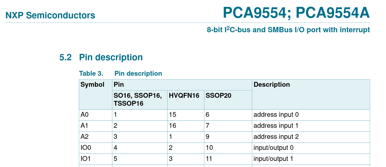
Having determined that these relate to pin 3, 2 and 1 respectively, we can now look back at the original schematic of the VEML3328 sensor board to see how Vishay have connected these three “address” pins.
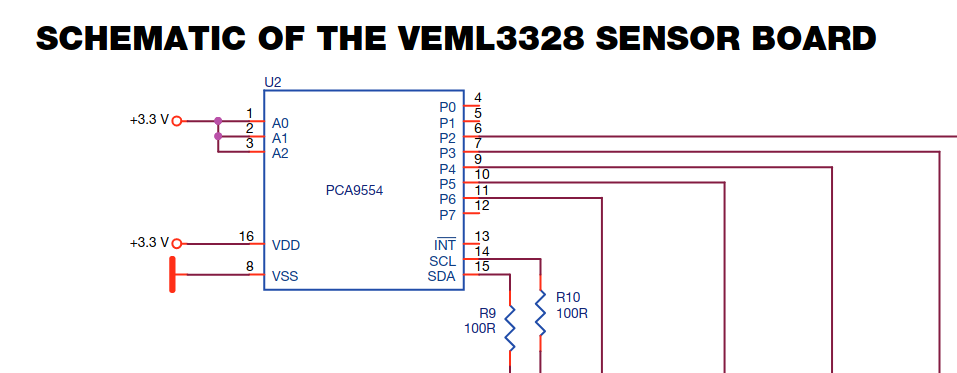
And here we can see that these pins are all pulled high (logic 1), so that means the 7-bit I2C slave address for the PCA9554 will be 0b0100111 = 0x47.
In summary:
- RGB LEDs are controlled using the GPIO controller on I2C slave address 0x47.
- Colour sensor measurements can be read from the VEML3328 on I2C slave address 0x10.
Setting up the Integrated Development Environment (IDE)
We have built our basic test circuit and gathered all the information we need to start writing code. The next step is to set up an IDE for building applications on the ESP32. A quick look at the ESP website and their getting start guide indicates that they provide a plugin for Eclipse and Visual Studio Code. If you are a software engineer then you will definitely have heard of both of these IDEs and more than likely used both of them too. If you are not familiar with these tools, then basically it is an application which runs on your PC and incorporates all the different tools that you will need to write programs, flash them to the processor, test, debug and release your code. Most integrate nicely with configuration management systems (such as git) too. I have used both of these IDEs considerably and they both work really well but each have their pros and cons. However, at the moment, my goto IDE is VSCodium the FOSS (Free Open Source Software) version of Microsoft Visual Studio Code. Since they both share the same common code base, their look and feel is almost identical and plugins (or extensions as they are called) are almost all compatible.
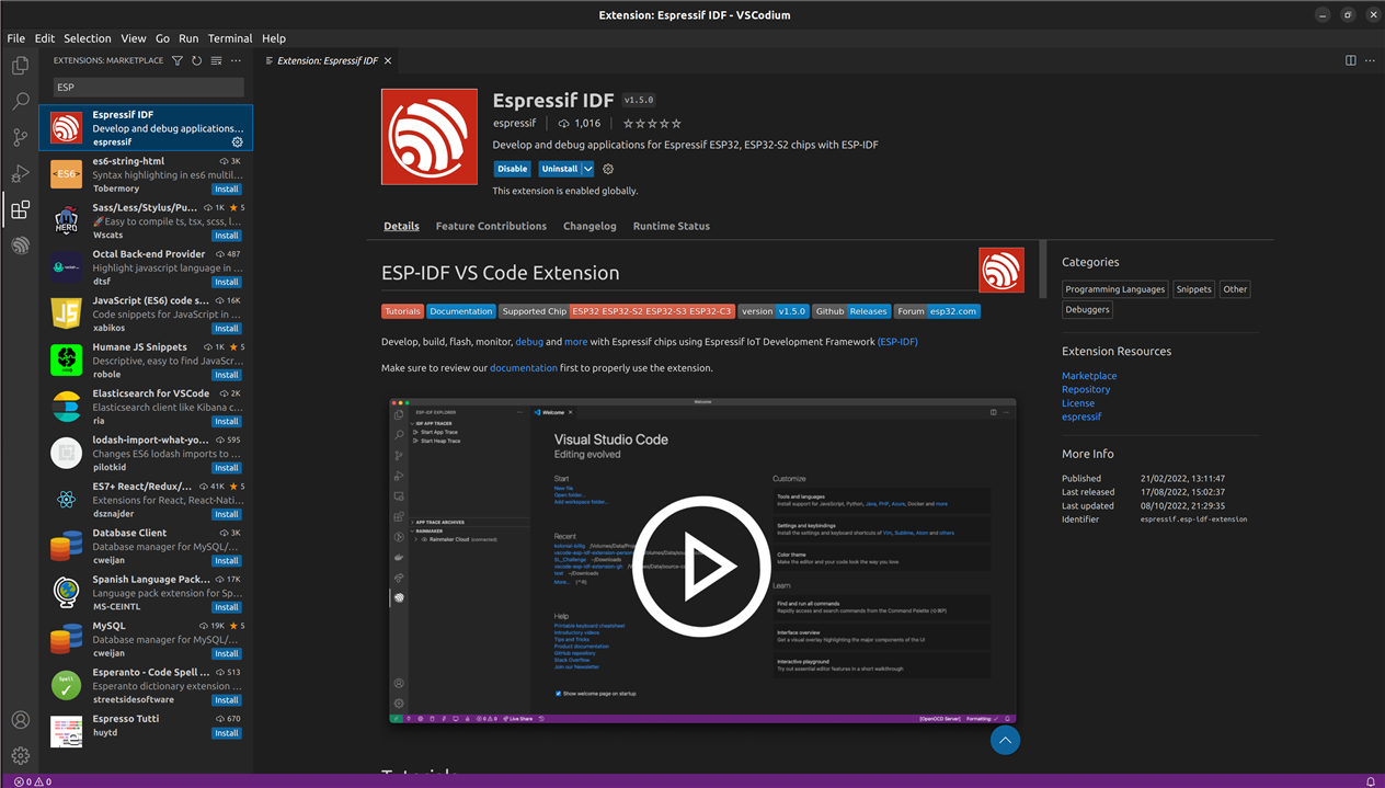
The first step in setting up the IDE will be to install the ESP extension in VSCodium. Start VSCodium, click on the extensions button on the left toolbar, search for “ESP” and click the “Install” button. It will take a few seconds to install and then you will get a page which looks something like this:
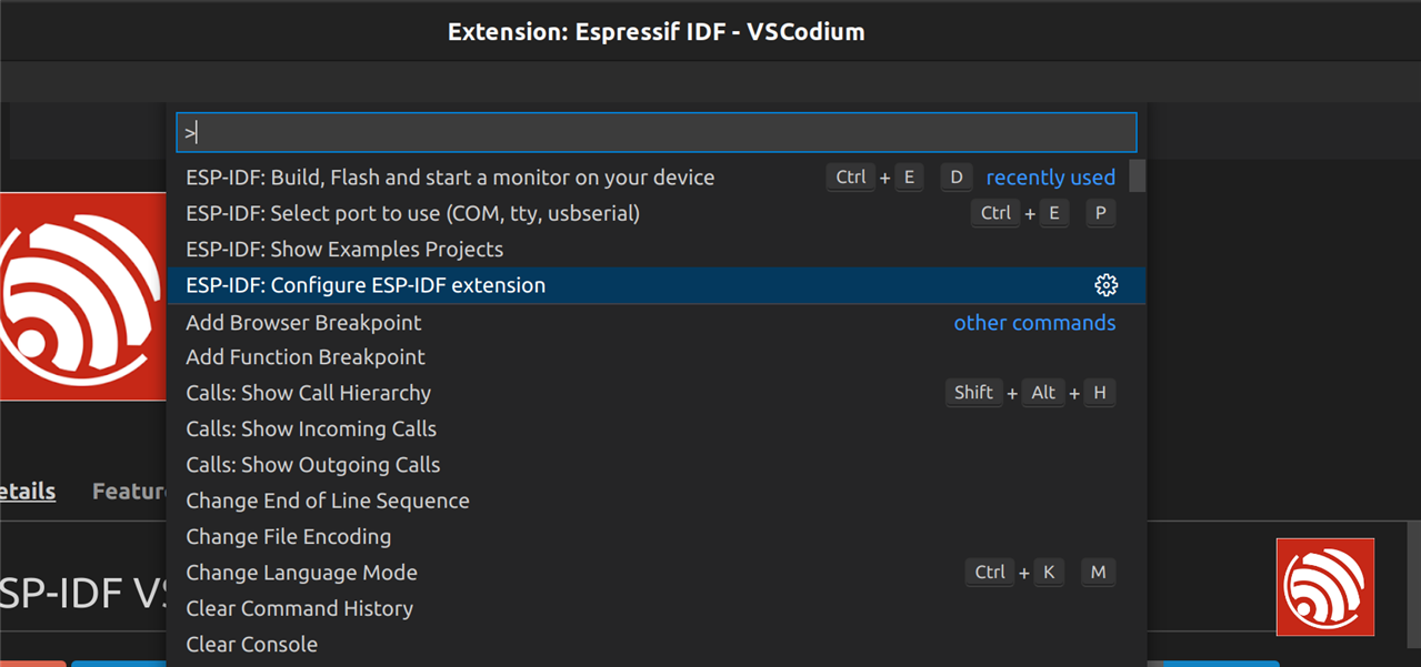
Once installed it will have added several new commands to the IDE which can be accessed through the command palette. This is opened from the menu bar by clicking “View”, “Command Palette”. Alternatively the shortcut key by default is “F1”. In the box that appears, type “ESP-IDF” and all of the new ESP commands that have been installed by this extension will be listed. To set things up we need to configure the new plugin, so the command we are looking for is: “ESP-IDF: Configure ESP-IDF extension”:
Click on the “Express” installation option and fill in the requested installation paths (the default is usually fine):
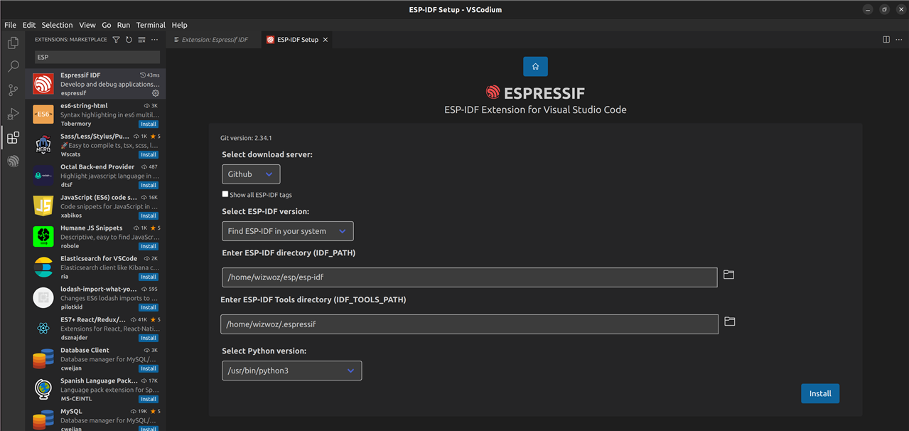
Click install, then go and make a cup of tea because it will be downloading 1GB of software development kit (SDK):
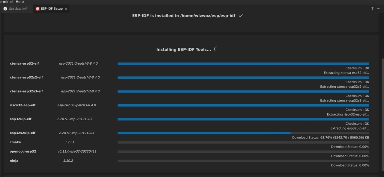
Creating an ESP Project
With the IDE now setup, a new project to target the ESP microcontroller can be created by running the “ESP-IDF: Show Examples Projects” command from the command palette:

After scrolling through the list of example projects, my eye caught sight of an I2C example project. Since today all I want to do is communicate with the VEML3328 sensor board, this seems like a good starting point for my project:
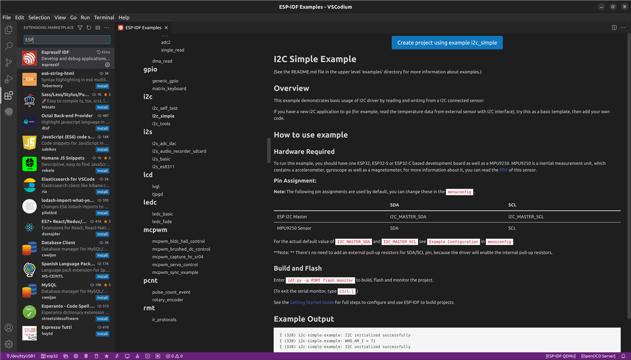
After clicking the “Create project using example i2c_simple” button, a new project is created. The main source files are contained within the “main” subdirectory. The entry point to the app is in “i2c_simple_main.c” as shown below:
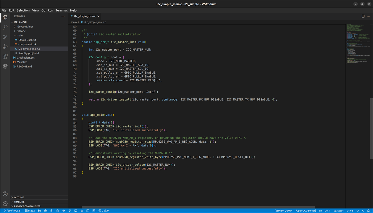
This example project attempts to connect to an MPU9250 which is an I2C accelerometer device. Obviously we do not have that connected so this example application won’t do anything too exciting but we can try building it, downloading (flashing) it to the ESP and running it. This can be achieved by running the “ESP-IDF: Build, Flash and start a monitor on your device” command from the command palette:

Alternatively, the ESP extension has also configured all the common commands as little tool buttons along the bottom taskbar:

Using this taskbar you can clean the project, build the project, run, debug etc. The first time you run the project it takes a while to build as it needs to build all the prerequisites, but after that, the build time is only a few seconds, then it will flash the ESP and open a terminal to view any debug or error information which the application prints.
Developing the VEML3328 Software
Looking through the example project, there was a lot of MPU9250 specific commands, so I stripped out all of that and created my own functions for controlling the RGB LED and reading the colour sensor, just keeping the common code required to set up an I2C master on the ESP.
I created the following source and headers files in the main subdirectory:
- main/pca9554.c/h, for controlling the PCA9554 GPIO controller
- main/veml3328.c/h, for controlling the VEML3328 colour sensor
- main/i2c_common.h, for the declaration of common I2C settings such as timeouts and bus frequency
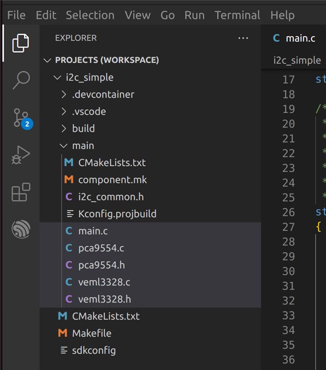
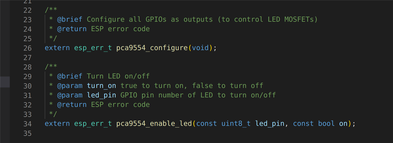
I defined the slave address and other configuration register settings for the two I2C devices in their respective header files. I also documented all the files, functions, variables and constants in code to make the auto-generation of documentation easy. The next screenshot shows a snippet of the header file I created for the PCA9554 device. The I2C slave address (as calculated earlier in this blog) is defined on line 8 as 0x27.

I then created two functions to control this device. The first performs some initialisation and configuration steps. The second provides a method to turn a specific LED on or off. I’m not entirely sure if I will need the RGB LED in this project – I hadn’t realised it had this LED on the board until I received the kit, so it wasn’t included in my original design. However, I can think of several useful features for an LED so I might well incorporate this in the final design. One idea I had for this LED was to use it to signal the WiFi status of the ESP32. For example if the ESP has failed to connect to the smart bulb or WiFi network, then I could illuminate the red LED; if the connection is good and ready to control the bulb then maybe a green LED. Since it is an RGB LED I can generate all the different colours so I can indicate all sorts of statuses and errors with it which will be very useful for debugging when it is in operation and the debug console is not connected.
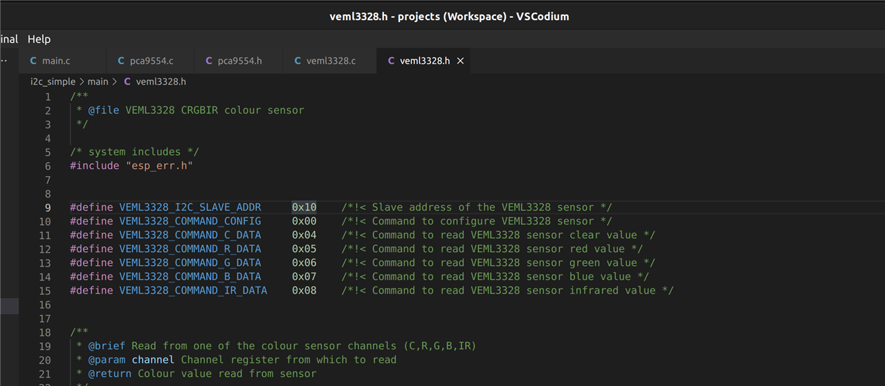
The next screenshot shows a snippet of the header file I created for the VEML3328 sensor. The I2C slave address (as found in the datasheet earlier) is defined on line 9 as 0x10.
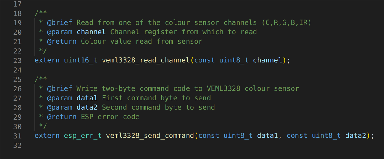
As with the other I2C device I created two useful functions to control the VEML3328 sensor. One function reads the value of one of the sensor channels (red, green, blue, clear or infrared). The other is used to initially configure the device. As before all functions are documented for auto doc generation.
Testing
This blog is already too long, so I’m not going to go into any more detail other than to show the main code loop. When the application loads, I have coded it to flash the RGB LED a few times then enter the main loop which periodically calls the functions created above to read from the colour sensor and print the results to the debug terminal.
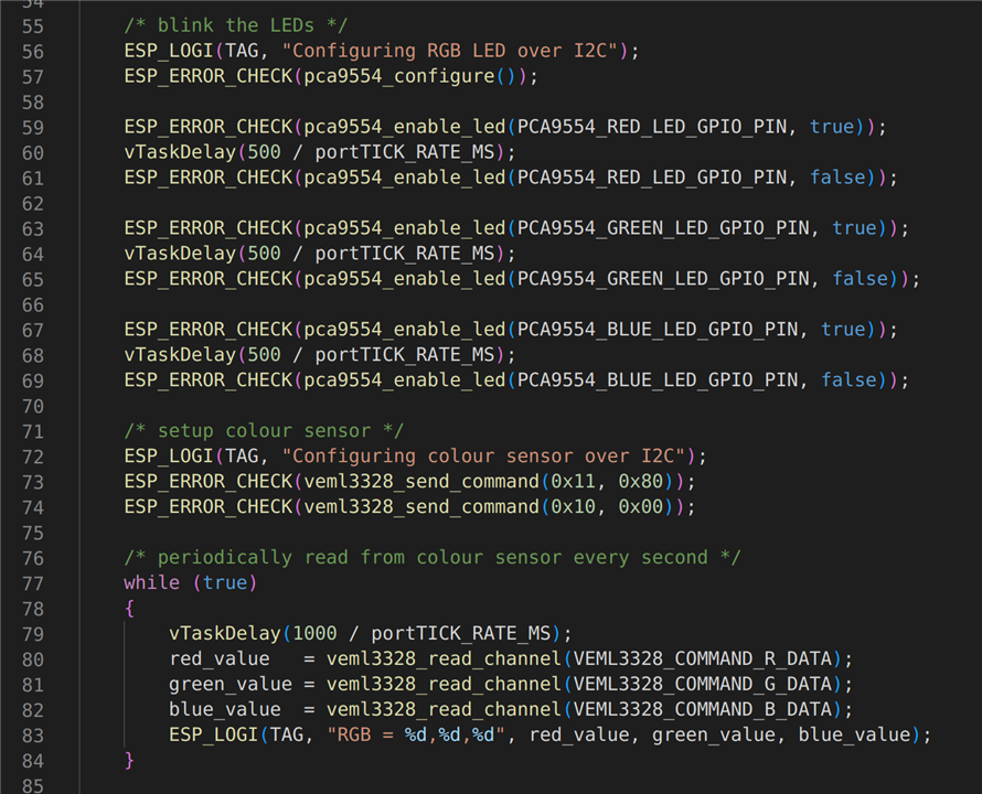
Now the code is all written we need to build it, flash it to the ESP, run it, and monitor the output.
Before the application can be download to the ESP, we need to plug it into a USB port using the micro-USB cable and tell the ESP-IDF extension which port it is connected to. I’m running Linux (of course), so this can be achieved by running “dmesg” immediately after plugging in the ESP to a USB port:
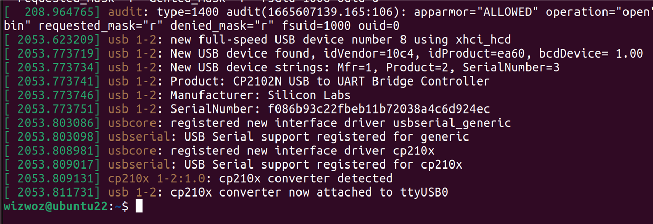
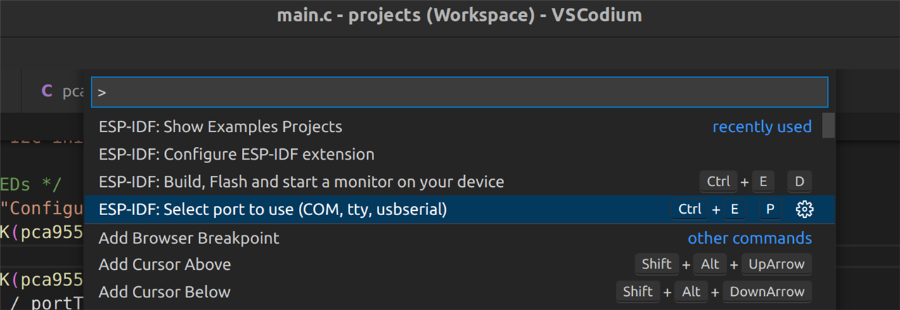
This log shows that a CP210X device (UART to USB bridge) has been connected to a USB port and is available on “/dev/ttyUSB0”. From the VSCodium command palette we can tell the ESP-IDF that we want to use “ttyUSB0” to access the ESP:
Finally run the “Build, flash and monitor” command (either from the command palette or the taskbar at the bottom of the IDE). The terminal window will show the progress of the build:
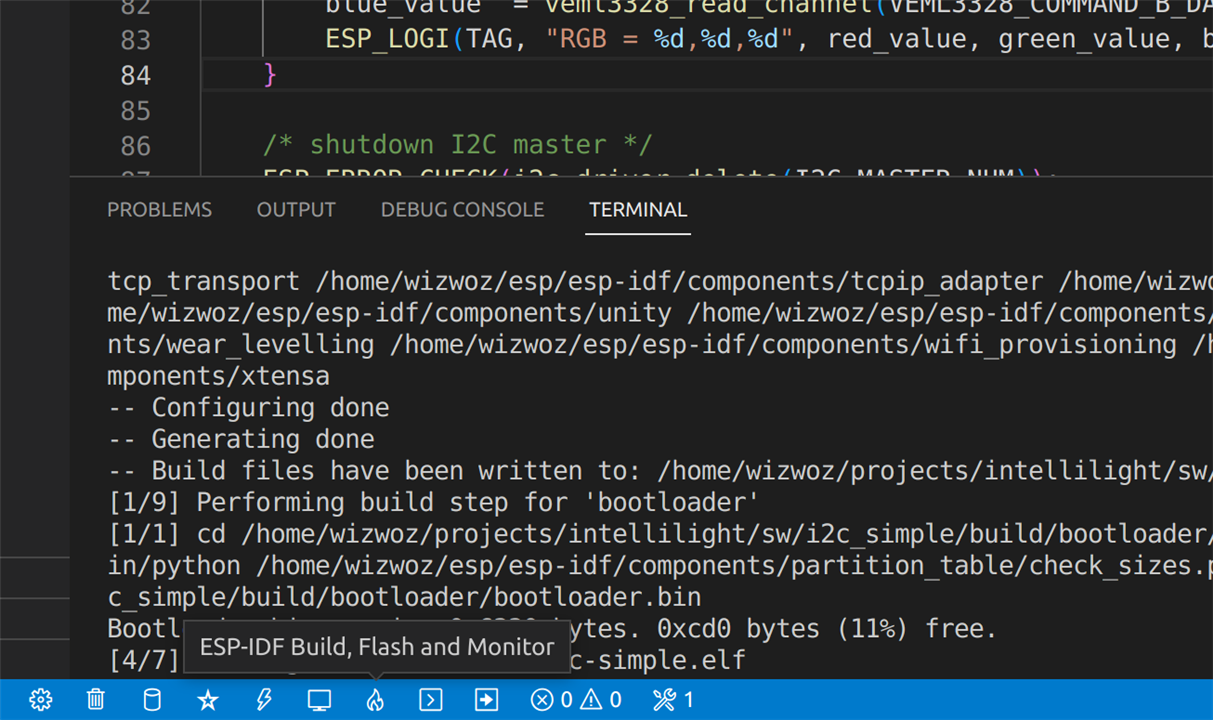
And after it has flashed the built firmware to the ESP the RGB LED on the Vishay VEML3328 sensor board flashes as expected and then the console starts printing out the value of the colour sensor every second. In the screenshot below I turn the light off for a few seconds and can clearly see the values of the red, green and blue components drop considerable. When I turn the room light back on, the values increase to their original high value.
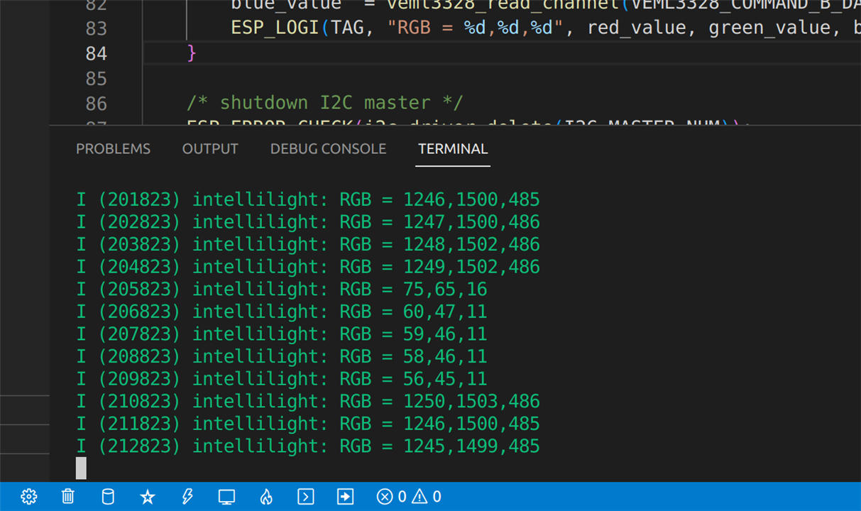
One quick observation from the values returned here. The light in this room is a normal incandescent (yellowish) bulb. Yellow is made from red and green. Looking at the red, green and blue values returned above, it can be seen that there is indeed very little blue detected and the red and green values are almost equal – which would indicate a yellow light!
Conclusion
As I wrap this blog up, I can conclude that manually communicating with the Vishay VEML3328 sensor board is very straightforward, required a very small amount of coding, and required very little knowledge of the I2C protocol. The datasheets were concise and clear - they provided just enough detail to learn the information required to set up this connection between the sensor and the ESP32. The data I have read back from the sensor seems to make sense. I’ve obviously not calibrated it, but from the small amount of testing I have done so far, it seems to have the accuracy required for my intended purpose. The VEML2238 sensor board has been very reliable so far and I’ve not run into any issues with it yet.
What’s Next
Today I have succeeded in controlling the RGB LED and reading the colour sensor using the ESP. The next step is to add the gesture sensor board (which also contains two devices – a proximity sensor and an ambient light sensor). I will need to repeat the same process: getting the datasheets, finding the power supply requirements, identifying the I2C slave address (and hoping they do not clash with the two I’ve already used!), and connect that up (in series) with the VEML3328 sensor board. I will be doing this in the next day or so, but I won’t blog the whole process since it will basically be identical to this one, but I will briefly post something to say whether it was successful and highlight any difficulties I may have encountered.
The next stage after that (which will be the topic of my next main blog) will be to test out the WiFi connection on the ESP32 device and experiment controlling a smart bulb from the ESP32 (plot-spoiler: I have already de-risked this and can control a smartbulb from a bit of python so hopefully it’s not too much effort to port it over to the ESP). That will be the last major stage of de-risking – if I can get each of those things working, it will just be a SW development task to get everything working together as a full system.
Many thanks for reading this blog, and as always, please feel free to comment below if you have any questions, tips or advice.
| Previous Blog (Part 4) | Next Blog (Part 6) |


-

Jan Cumps
-
Cancel
-
Vote Up
0
Vote Down
-
-
Sign in to reply
-
More
-
Cancel
Comment-

Jan Cumps
-
Cancel
-
Vote Up
0
Vote Down
-
-
Sign in to reply
-
More
-
Cancel
Children