


Welcome
Hello everyone and welcome back to my 2nd to last blog for this competition. It has been a fun and informative journey, and I hope I will be able to compete again some time. Last post I announced that the SensorXplorer sensors (VEML3328 Color sensor & VCNL4035X01 Gesture/Proximity board) were shipped to me in good condition, and I was able to do a few data tests. This week I will show you how I was able to integrate both sensors into my Arduino code, and the discoveries I made along the way. Let's check it out!
Arduino Sensor Intergration
I originally was going to try to use the Arduino Wire library (Arduino's built in I2C library) to communicate with the sensors, but soon found that there were already library's out for each of these sensors. I used the VEML3328 library from Developium, and the VCNL4035X01 library from LukeYoung3000. Both are available on GitHub to download for free and allow simple use of the sensors. Here is the full Arduino code:
//proximity sensor libraries
#include <VCNL4035_App.h>
#include <vcnl4035_Defs.h>
#include <VCNL4035_Lib.h>
#include <VCNL4035_Types.h>

#include <VEML3328.h>

//Color sensor:
//1. Start by getting the values from the color sensor channels R, G, & B
//2. Check what range each is in by dividing them into two groups, High & Low. The low range is < 2/3rds of the max detection, High range is > 2/3rds max detection. (Note: this may change depending on later adjustments)
//3. Send this info to the raspberry pi by setting the correct pins to either high (3.3v) or low (0v).
//4. Repeat every 60 seconds, as most songs are not shorter than this.

//Backup sensor
//1.Start by getting the proximity data from the sensor.
//2.Since the range of the proximity sensor is 500mm - 0mm, I am going to divide it into three ranges: Far = 500mm - 332mm, Medium = 332 - 166, Close = 166 - 0mm. Store this in a variable.
//3.Depending upon the proximity send pulses to the buzzer. Far = 0 pulses/repetition, Medium = 1 pulse/repetition, Close = 2 pulses/repetition.
//4. Repeat every 2 seconds.

//Color Sensor object
VEML3328 RGBCIR;

// Create VCNL4035 object (Proximity Sensor)
VCNL4035 vcnl;
uint16_t proxy_data[3] = {0};

//Pins to output color logic
const int redpin = 5;
const int greenpin = 6;
const int bluepin = 7;

//Pin for buzzer
const int buzzpin = 9;

//Uses this as an example of proximity. I will have it loop through proximitys as if an object is back and forth in front of it. It starts out far away, at 500 mm.
int proximity = 500;
bool incrementing = false;

unsigned long previousMillis = 0;        // will store last time buzzer was updated

//intervals used:
const long interval1 = 1000;           // interval at which to buzz (milliseconds)
const long interval2 = 2000;

int BuzzState = 0;//state of buzzer, 1 = on, 0 = off


//which color is the highest (Red = 0, Green = 1, Blue = 2)
int highestColor = 0;

void setup()
{
   //for debug
  Serial.begin(115200);
  //set up pins to control music playing
  pinMode(redpin,OUTPUT);
  pinMode(greenpin,OUTPUT);
  pinMode(bluepin,OUTPUT);

  //set up pin for buzzer
  pinMode(buzzpin,OUTPUT);

  //set up color sensor library settings
  //make sure color sensor is connected
  if(!RGBCIR.begin()) {
    Serial.println("Couldn't detect the sensor");
    while(1){}
  }
  Serial.println("Enabling sensor");
  RGBCIR.Enable();                    //enable the sensor channels
  RGBCIR.setGain(4);                  //set the amplification gain to 4
  RGBCIR.setSensitivity(high_sens);   //set the sensitivity mode (
  RGBCIR.setDG(2);                    //set the digital gain
  RGBCIR.setIntegrationTime(IT_50MS); //set the sensor's integration time or the time it takes to take one measurement (IT_100MS, IT_200MS, IT_400MS can also be selected)
  // Set up VCNL registers
  vcnl.init(PROXIMITY_SENSOR);
  // Change the Integration time to the largest possible time (8T)
  vcnl.setPsIntegrationTime(PS_IT_400us);
  //This is needed for while sensor starts up
  delay(1000);
}

void loop() {
//Color Sensor Logic
  //read data from color sensors
  int Rval = RGBCIR.getRed();
  int Gval = RGBCIR.getGreen();
  int Bval = RGBCIR.getBlue();


//  //attune for the fact that red and green are over presented
//  Rval = Rval/20;
//  Gval = Gval/10;

  //debug 4 colors
  Serial.println("R: "+String(Rval));
  Serial.println("G: "+String(Gval));
  Serial.println("B: "+String(Bval));

  //define variables
  bool Rhigh = false;
  bool Ghigh = false;
  bool Bhigh = false;

  //update highest value and which color that is
  updateHighestColor(Rval,Gval,Bval);

  //get distances between colors
  int distRG = abs((Rval-Gval));
  int distGB = abs((Gval-Bval));
  int distBR = abs((Bval-Rval));

  //get the lowest value, this tells us what colors are closest
  int closestColors = min(min(distRG,distGB),distBR);


  //update pins based on color
  if (0 == highestColor && closestColors == distGB) {Rhigh = true;} //red
  if (1 == highestColor && closestColors == distBR) {Ghigh = true;} //green
  if (2 == highestColor && closestColors == distRG) {Bhigh = true;}//blue
  //color combinations
  if ((1 == highestColor || 2 == highestColor)&& closestColors == distRG) {Rhigh = true; Ghigh = true;}//yellow (if red or green is the highest color and they are the closest together)
  if ((2 == highestColor || 3 == highestColor)&& closestColors == distGB) {Rhigh = true; Ghigh = true;}//cyan (if blue or green is the highest color and they are the closest together)


  //debug for asessment
  Serial.println("Rpin: "+String(Rhigh));
  Serial.println("Gpin: "+String(Ghigh));
  Serial.println("Bpin: "+String(Bhigh));

  //relate it to pins (the raspberry pi reads these and relates them to the color, so we dont need to do that) This does set the pins to 5v on high, so we will have to use a logic level converter
  digitalWrite(redpin,Rhigh);
  digitalWrite(greenpin,Ghigh);
  digitalWrite(bluepin,Bhigh);

//Backup Sensor Logic
  //update proximity
  vcnl.readGestureData(proxy_data);
  proximity = proxy_data[0];

  //debug proximity
  Serial.println(proximity);


  //proximity number increases as object gets closer.
  if(proximity < 15)
  {
    //Far: Buzz 0 times/second
    noTone(buzzpin);
    BuzzState = 0;
  }
  else if(proximity < 65)
  {
    //Medium: Buzz 1 time every 2 seconds
    unsigned long currentMillis = millis();
    if (currentMillis - previousMillis >= interval2) { //every two seconds
      // save the last time you blinked the LED
      previousMillis = currentMillis;
      // if the buzzer is off turn it on and vice-versa:
      if (BuzzState == 0) {
        BuzzState = 1;
        tone(buzzpin,256);
      } else {
        BuzzState = 0;
        noTone(buzzpin);
      }
    }
  }
  else //proximity is greater then 65, so it is close
  {
    //Close: 2 times/2 seconds (Once a second)
    unsigned long currentMillis = millis();
    if (currentMillis - previousMillis >= interval1) { //every second
      // save the last time
      previousMillis = currentMillis;
      // if the buzzer is off turn it on and vice-versa:
      if (BuzzState == 0) {
        BuzzState = 1;
        tone(buzzpin,256);
      } else {
        BuzzState = 0;
        noTone(buzzpin);
      }
    }
  }


  //debug buzzer
  Serial.println("Buzz state:" + String(BuzzState));
}

//update the two variables highestColorValue and highestColor
void updateHighestColor(int redVal,int greenVal,int blueVal)
{
  int maxvalueRG = max(redVal,greenVal);
  int maxvalue = max(maxvalueRG,blueVal);

  //get which color that is
  if(maxvalue == redVal)
  {
    //red
    highestColor = 0;
  }
  else if(maxvalue == greenVal)
  {
    highestColor = 1;
  }
  else
  {
    //blue
   highestColor = 2;
  }
}
I updated the code to read from the sensors instead of random values, using their respective libraries.
//read data from color sensors
  int Rval = RGBCIR.getRed();
  int Gval = RGBCIR.getGreen();
  int Bval = RGBCIR.getBlue();

  .....

  //update proximity
  vcnl.readGestureData(proxy_data);
  proximity = proxy_data[0];
Originally my code used the delay function to buzz at the correct intervals, but that slowed down the readings. This is a common problem with many Arduino problems: How to do an action at a set interval without using the delay function? The answer can be found in Arduino's BlinkWIthoutDelay example, which uses the millis() function to check the time and call a function at a set interval.
if (currentMillis - previousMillis >= interval1) { //every second
      // save the last time called
      previousMillis = currentMillis;
      // if the buzzer is off turn it on and vice-versa:
      if (BuzzState == 0) {
        BuzzState = 1;
        tone(buzzpin,256);
      } else {
        BuzzState = 0;
        noTone(buzzpin);
      }
    }
This allows me to turn the buzzer on and off at the time I want without stopping the readings from the sensors. The last big change was the way I determine what color is most present.
  //update highest value and which color that is
  updateHighestColor(Rval,Gval,Bval);

  //get distances between colors
  int distRG = abs((Rval-Gval));
  int distGB = abs((Gval-Bval));
  int distBR = abs((Bval-Rval));

  //get the lowest value, this tells us what colors are closest
  int closestColors = min(min(distRG,distGB),distBR);


  //update pins based on color
  if (0 == highestColor && closestColors == distGB) {Rhigh = true;} //red
  if (1 == highestColor && closestColors == distBR) {Ghigh = true;} //green
  if (2 == highestColor && closestColors == distRG) {Bhigh = true;}//blue
  //color combinations
  if ((1 == highestColor || 2 == highestColor)&& closestColors == distRG) {Rhigh = true; Ghigh = true;}//yellow (if red or green is the highest color and they are the closest together)
  if ((2 == highestColor || 3 == highestColor)&& closestColors == distGB) {Rhigh = true; Ghigh = true;}//cyan (if blue or green is the highest color and they are the closest together)
I first take the highest color value, and then check the distance between all the color levels. For example, if red is the highest color and green & blue are closest together, I would say that the most prominent color is red. If red is the highest (or green) but red and green are the closest together, that would be yellow, as green and red make yellow. This model works for all colors but white. From my readings White is usually read as blue with this model, which is a small downside, but should be okay, as I don't get much snow here. (;
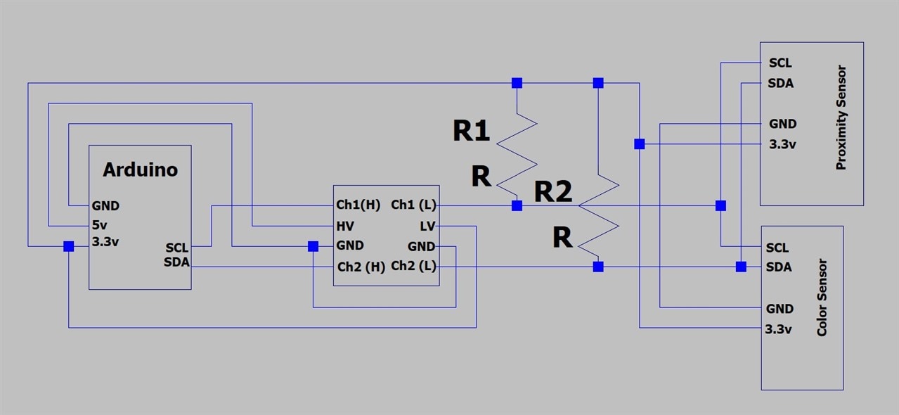
Circuit
Here is a diagram of the circuit I am using; it doesn't require much extra circuitry. For the Arduino Uno it uses 5 volts as logic high, but that could possibly damage the sensors, as they use 3.3v. This is the same problem I had with the Raspberry Pi and the Arduino, which can be easily solved by either a logic level board or a voltage divider. I also have pullup resistors on each of the I2C lines, each with a value of 3.3K ohms.
Thanks for Reading!
I hope you liked this post, next week I will hopefully show how I will install the sensors on the golfcart, as well as my possible future upgrades. Have a great day.

