


Introduction
This is the fourth blog post for the Summer of Sensors Design Challenge. In this blog post, I will interface the LSM6DSL Click with Arduino. LSM6DSL click measures linear and angular velocity with six degrees of freedom. It carries the LSM6DSL high-performance 3-axis digital accelerometer and 3-axis digital gyroscope. LSM6DSL click communicates with the target microcontroller over SPI or I2C interface, with additional functionality provided by the INT pin on the mikroBUS line. The default mode of the sensor is SPI. So, I am going to use the SPI protocol for interfacing the sensor with Arduino. I will use this sensor click in my project for counting steps, detecting free fall, and tracking sleep. All these parameters are closely related to health. I will make a separate wearable unit for getting these three parameters and the data will be transferred to the main unit using Bluetooth.
Why Fall Detection, Sleep & Activity Tracking are Important?
Fall detection is a major challenge in the public healthcare domain, especially for the elderly as the decline of their physical fitness, and timely and reliable surveillance is necessary to mitigate the negative effects of falls. Falling can create serious injury in the elderly population and in the United States, around 33% of the elderly fall at least once per year, and these falls result in over 2 million visits to the emergency room. So monitoring all these parameters is very important.
Physical activity and movement are a must for improving health and reducing the risk of developing several diseases like type 2 diabetes, cancer, and cardiovascular disease. Physical activity and exercise can have immediate and long-term health benefits. Most importantly, regular activity can improve your quality of life. A minimum of 30 minutes of walking a day can allow you to enjoy these benefits. So, you need to keep track of your step.
Sleep directly impacts your immune system and your ability to fight off infections like covid-19. As you rest, you are helping to make your body whole and healthy again. Your immune system works to fight against harmful germs. It also helps to fight against changes within the body, such as cell mutation (cancer). A lack of sleep causes degenerative effects throughout the entire body, so the immune system will not work as efficiently when you are sleep deprived. So, you should know if your sleep is adequate or not. LSM6DSL click uses LSM6DSL high-performance 3-axis digital accelerometer and 3-axis digital gyroscope. So, LSM6DSL is a perfect choice for measuring all those three important parameters.
How to Measure Those
The easiest way to measure all the above parameters is to use 3-axis digital accelerometer and 3-axis digital gyroscope. A 3-axis accelerometer and gyroscope can give an accurate measurement of activity and free fall. For tracking sleep accurately accelerometer and gyroscope itself are not enough but we can get a good idea about sleep time and quality using this mems sensor.
The LSM6DSL Click
LSM6DSL click measures linear and angular velocity with six degrees of freedom. It carries the LSM6DSL high-performance 3-axis digital accelerometer and 3-axis digital gyroscope. The click is designed to run on a 3.3V power supply. LSM6DSL click communicates with the target microcontroller over SPI or I2C interface, with additional functionality provided by the INT pin on the mikroBUS line.

The LSM6DSL is a system-in-package featuring a 3D digital accelerometer and a 3D digital gyroscope performing at 0.65 mA in high-performance mode and enabling always-on low-power features for an optimal motion experience.
The event-detection interrupts enable efficient and reliable motion tracking and contextual awareness, implementing hardware recognition of free-fall events, 6D orientation, click and double-click sensing, activity or inactivity, and wake-up events. The LSM6DSL has a full-scale acceleration range of ±2/±4/±8/±16 g and an angular rate range of ±125/±245/±500/±1000/±2000 DPS (degrees per second). The sensor is super-flexible and can be configured specifically for an application.
Some of the things the LSM6DSL can do:
- Read accelerometer data for super-accurate movement sensing
- Read temperature
- Buffer up to 4 kbytes of data between reads (built-in FIFO)
- Count steps (Pedometer)
- Detect shocks, tilt, motion, taps, double-taps, and free fall
- Host other sensors into its FIFO
- Drive interrupt pins by embedded functions or by FIFO low-capacity/overflow warning.
Interfacing with Arduino
LSM6DSL sensor can communicate with a microcontroller using both SPI and I2C. The default configuration of the LSM6DSL click board is SPI. So, I am going to use SPI protocol to interface the click board with Arduino. Both slots of the Arduino click shield will work. For this experiment, I used slot 2 of the click board. For working with Arduino first you need to install the Arduino library for the LSM6DSL. The library can be downloaded from the following GitHub link (the LSM6DSL Library GitHub). This library will work for both I2C and SPI. The library has the readymade example for step count and free fall. Sleep tracking algorithm should be implemented by the user.
Example program for step count (modified for SPI)
// Includes.
#include <SPI.h>
#include <LSM6DSLSensor.h>

#define SerialPort Serial
#define CS_PIN 9

// Components.
LSM6DSLSensor AccGyr(&SPI, CS_PIN);

//Interrupts.
volatile int mems_event = 0;

uint32_t previous_tick = 0;
uint32_t current_tick = 0;
uint16_t step_count = 0;
char report[256];

void INT1Event_cb();

void setup() {
  // Led.
  pinMode(LED_BUILTIN, OUTPUT);

  // Initialize serial for output.
  SerialPort.begin(9600);

  // Initialize I2C bus.
  SPI.begin();

  //Interrupts.
  attachInterrupt(INT1, INT1Event_cb, RISING);

  // Initlialize Components.
  AccGyr.begin();
  AccGyr.Enable_X();

  // Enable Pedometer.
  AccGyr.Enable_Pedometer();

  previous_tick = millis();
}

void loop() {
  if (mems_event)
  {
    mems_event = 0;
    LSM6DSL_Event_Status_t status;
    AccGyr.Get_Event_Status(&status);
    if (status.StepStatus)
    {
      // New step detected, so print the step counter
      AccGyr.Get_Step_Counter(&step_count);
      snprintf(report, sizeof(report), "Step counter: %d", step_count);
      SerialPort.println(report);

      // Led blinking.
      digitalWrite(LED_BUILTIN, HIGH);
      delay(100);
      digitalWrite(LED_BUILTIN, LOW);
    }
  }

  // Print the step counter in any case every 3000 ms
  current_tick = millis();
  if((current_tick - previous_tick) >= 3000)
  {
    AccGyr.Get_Step_Counter(&step_count);
    snprintf(report, sizeof(report), "Step counter: %d", step_count);
    SerialPort.println(report);
    previous_tick = millis();
  }
}

void INT1Event_cb()
{
  mems_event = 1;
}
Example program for free fall detection (modified for SPI)
// Includes.
#include <SPI.h>
#include <LSM6DSLSensor.h>

#define SerialPort Serial
#define CS_PIN 9

// Components.
LSM6DSLSensor AccGyr(&SPI, CS_PIN);

//Interrupts.
volatile int mems_event = 0;

void INT1Event_cb();

void setup() {
  // Led.
  pinMode(LED_BUILTIN, OUTPUT);

  // Initialize serial for output.
  SerialPort.begin(9600);

  // Initialize I2C bus.
  SPI.begin();

  //Interrupts.
  attachInterrupt(INT1, INT1Event_cb, RISING);

  // Initlialize Components.
  AccGyr.begin();
  AccGyr.Enable_X();

  // Enable Free Fall Detection.
  AccGyr.Enable_Free_Fall_Detection();
}

void loop() {
  if (mems_event) {
    mems_event = 0;
    LSM6DSL_Event_Status_t status;
    AccGyr.Get_Event_Status(&status);
    if (status.FreeFallStatus)
    {
      // Led blinking.
      digitalWrite(LED_BUILTIN, HIGH);
      delay(200);
      digitalWrite(LED_BUILTIN, LOW);

      // Output data.
      SerialPort.println("Free Fall Detected!");
    }
  }
}

void INT1Event_cb()
{
  mems_event = 1;
}
Example sketch for single tap detection (modified for SPI)
// Includes.
#include <SPI.h>
#include <LSM6DSLSensor.h>
#define SerialPort Serial
#define CS_PIN 9
// Components.
LSM6DSLSensor AccGyr(&SPI, CS_PIN);
//Interrupts.
volatile int mems_event = 0;
void INT1Event_cb();
void setup() {
// Led.
pinMode(LED_BUILTIN, OUTPUT);
// Initialize serial for output.
SerialPort.begin(9600);
// Initialize I2C bus.
SPI.begin();
//Interrupts.
attachInterrupt(INT1, INT1Event_cb, RISING);
// Initlialize Components.
AccGyr.begin();
AccGyr.Enable_X();
// Enable Single Tap Detection.
AccGyr.Enable_Single_Tap_Detection();
}
void loop() {
if (mems_event) {
mems_event = 0;
LSM6DSL_Event_Status_t status;
AccGyr.Get_Event_Status(&status);
if (status.TapStatus)
{
// Led blinking.
digitalWrite(LED_BUILTIN, HIGH);
delay(100);
digitalWrite(LED_BUILTIN, LOW);
// Output data.
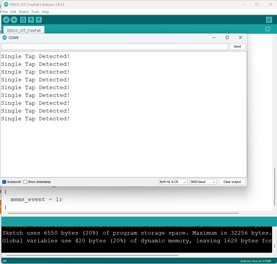
SerialPort.println("Single Tap Detected!");
}
}
}
void INT1Event_cb()
{
mems_event = 1;
}
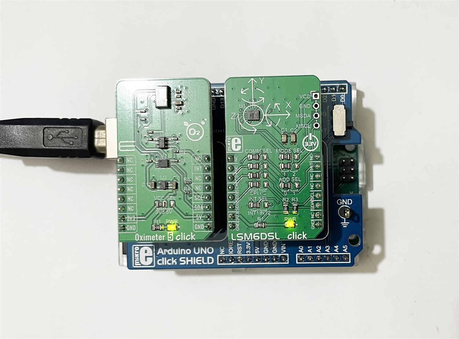
Connection with Arduino:
Serial monitor output:
Conclusion
In my next blog, I will make a wearable unit using Arduino Nano and LSM6DSL click for step count, free-fall detection, and sleep tracking. That unit will be a separate battery-powered unit that will be worn by the user. The unit will send the measured data to the main unit through Bluetooth with a double tap or button press on the device.