Introduction
In this blog post, I will share and explain the wearable unit of my remote patient monitoring system. This unit is designed to count the total steps made by the user, track sleep and detect any free falls. This unit sends the data to the main unit which is responsible for uploading the data to the cloud. This wearable unit is battery power and communicates with the main unit through Bluetooth. When the user double tap on the device it immediately sends the data to the main unit. The unit has an OLED display through which the user can observe the steps count, sleep quality, sleep duration, time, etc., and the options can be changed by single tapping on the device. I utilize the single tap and double tap without using any physical buttons.
The system used MikroElektronika's LSM6DSL Click board for all activity and sleep tracking. Its functionality and a few sample example codes are discussed in the previous blog.
Components used in this Unit
Here is the list of the components I used for the wearable unit.
| {tabbedtable}Components | Description |
|---|---|
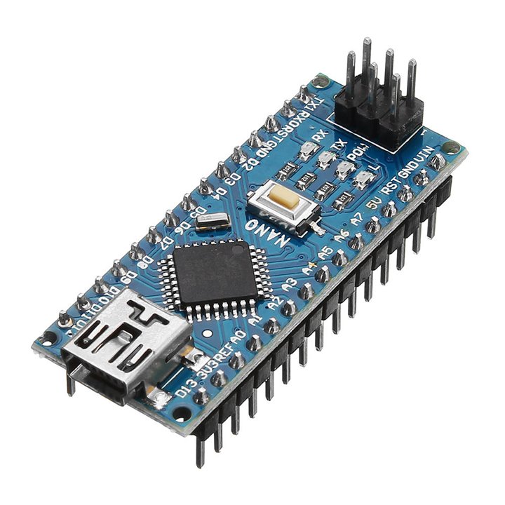
| Arduino Nano |
The Arduino Nano is the brain of this unit. It collects the data from the sensor, displays the useful information to the display, and sends the data to the main unit through Bluetooth. The reason for using the Arduino Nano here is its small form factor. As this is a wearable unit the size should be as small as possible.
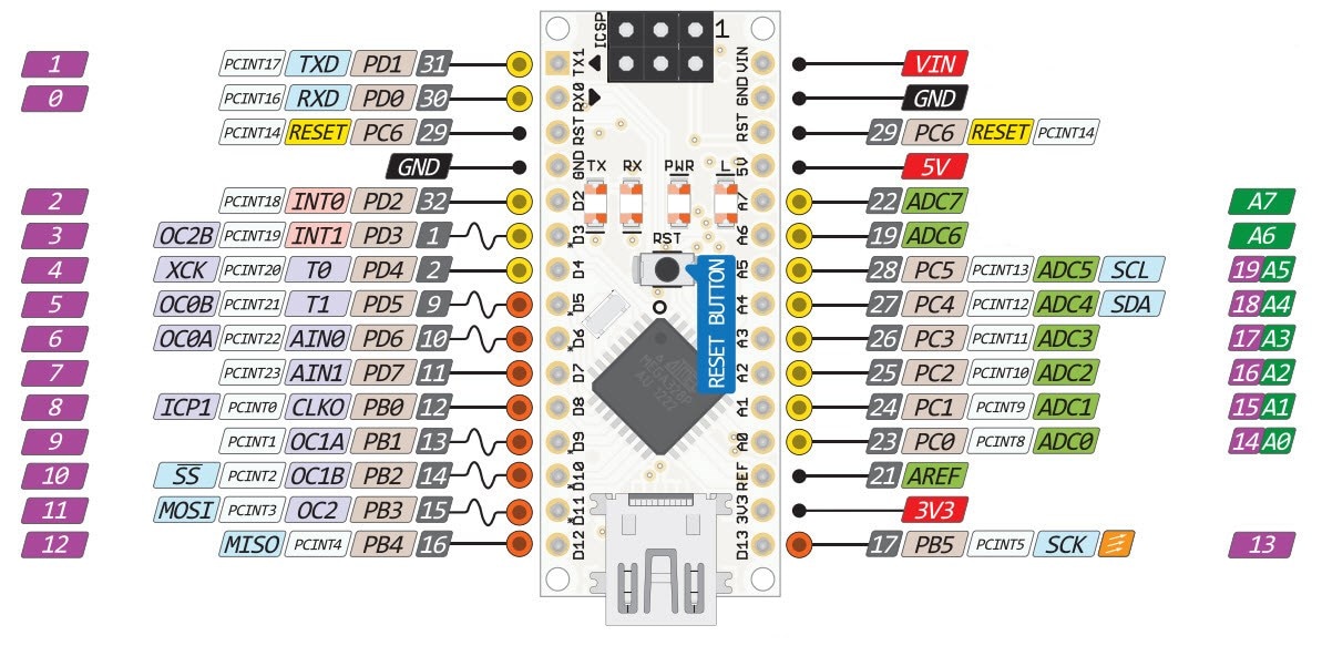
Arduino Nano Pinout
Arduino Nano Official Link: https://store.arduino.cc/products/arduino-nano |
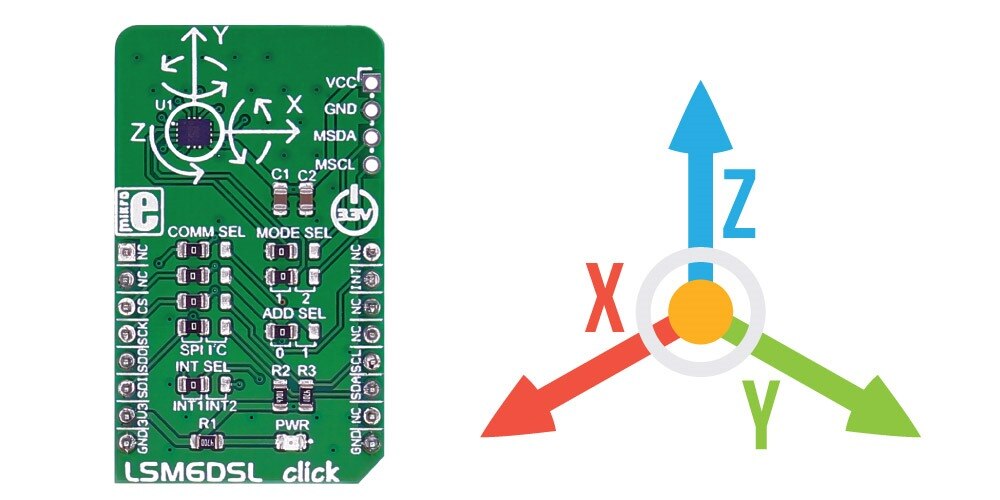
| LSM6DSL |
This component is another important element of the project. This is a high-performance 3-axis digital accelerometer and 3-axis digital gyroscope from MikroElektronika. The click is designed to run on a 3.3V power supply. LSM6DSL click communicates with the target microcontroller over SPI or I2C interface. I used this sensor here for activity detection, fall detection, and sleep tracking. Details of the sensor and its working was discussed in my previous blog.
Official link: https://www.mikroe.com/lsm6dsl-click |
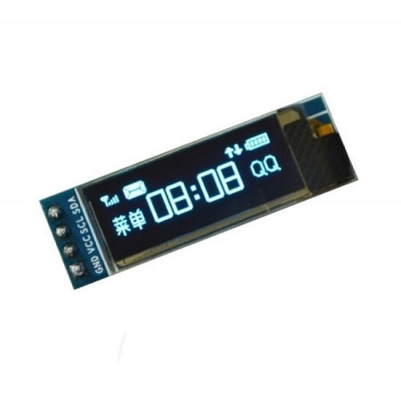
| 128x32 OLED Display |
These displays are small, only about 1" diagonal, but very readable due to the high contrast of an OLED display. This display is made of 128x32 individual white OLED pixels, each one is turned on or off by the controller chip. Because the display makes its own light, no backlight is required. This reduces the power required to run the OLED and is a perfect choice for the wearable devices. The driver chip of the display is SSD1306 and it communicates via I2C only.
Details of the display: https://www.adafruit.com/product/931 |
| HC-05 Bluetooth Module |
The HC-05 is a popular module that can add two-way (full-duplex) wireless functionality to any electronic project. You can use this module to communicate between two microcontrollers like Arduino or communicate with any device with Bluetooth functionality like a Phone or Laptop. There are many android applications that are already available which makes this process a lot easier. The module communicates with the help of USART at a 9600 baud rate hence it is easy to interface with any microcontroller that supports USART. This module can be configured to operate as Master or Slave mode. I am using it as a master device for my wearable unit.
Details of the module: https://howtomechatronics.com/tutorials/arduino/arduino-and-hc-05-bluetooth-module-tutorial/ |
| Logic Level Converter |
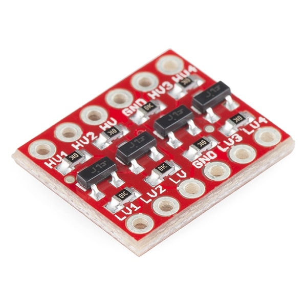
This bi-directional logic level converter can be used to connect a 3.3V device to a 5V system, you know what a challenge it can be. The SparkFun bi-directional logic level converter is a small device that safely steps down 5V signals to 3.3V AND steps up 3.3V to 5V at the same time. This level converter also works with 2.8V and 1.8V devices. We are using it here because the Arduino Nano works at 5V and every digital pin provides 5V to any connected system. On the other side, the LSM6DSL click board operates 3.3V. So, providing 5V to any pins of the click board or connecting it to any 5V system like Arduino Nano can damage the LSM6DSL. So, for the protection of the LSM6DSL click, we are using this logic-level converter here.
Details can be found here: https://www.sparkfun.com/products/12009 |
| Li-ion Battery |
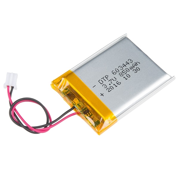
This system is a battery power device as the user will wear it. I used a li-ion battery for the unit. But the problem here is that the li-ion battery has an output voltage of 3.7V. This 3.7V is not compatible with Arduino nano. That means we can not directly connect the battery to the Nano. Either we need to step up the voltage to 5V or we need to step down the voltage at 3.3V. Besides, the li-ion battery needs a sophisticated battery management unit for safe charging and discharging. The power bank circuit has all this functionality on a single PCB.
Li-ion battery charging: https://batteryuniversity.com/article/bu-409-charging-lithium-ion |
| Power Bank Circuit |
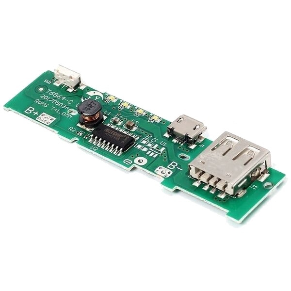
This power bank charger circuit has an integrated battery charger and a 5V boost converter. So, it is serving both the purposes required for our system.
|
Here are all the components I am going to use for the wearable unit.
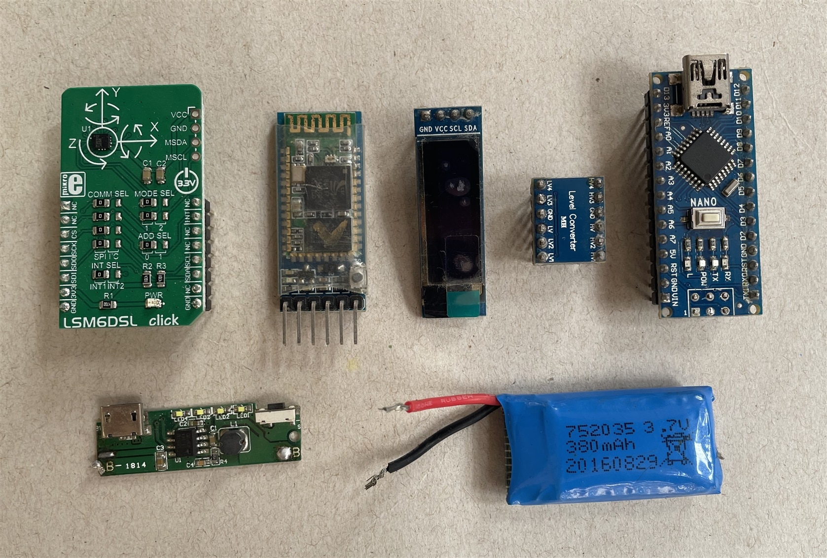
Without those main components, I will also use some basic components like resistors, pin header, jumper wire, and a perf board.
The Schematic
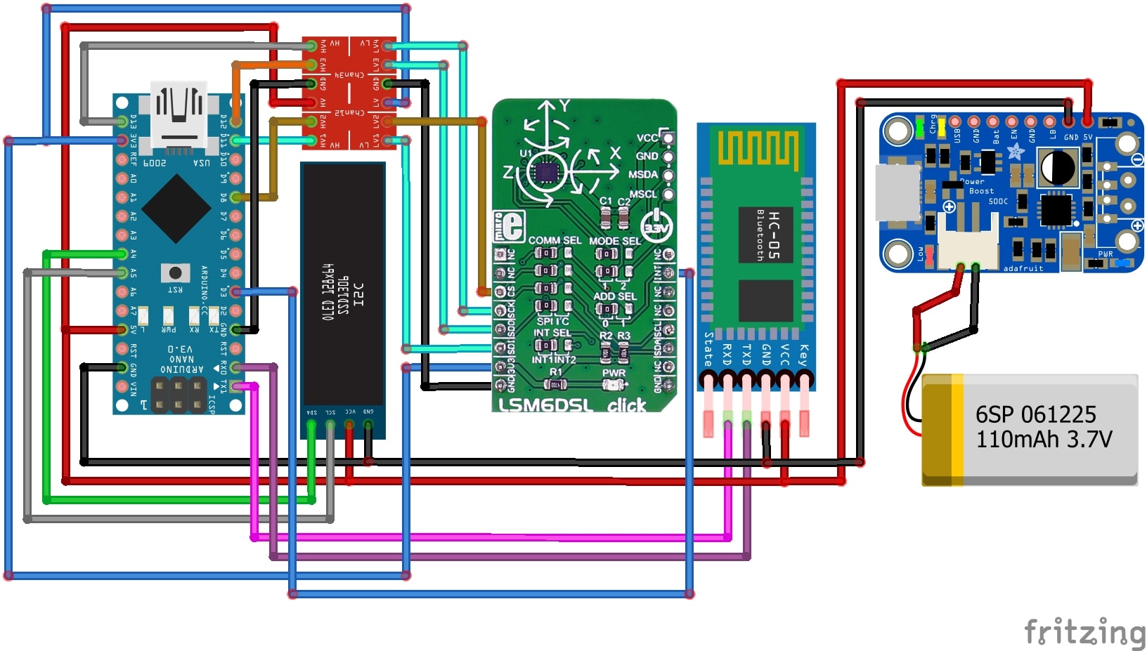
Here is the Fritzing schematic for the wearable unit of the remote patient monitoring system.
Making the Device
As this part is a wearable device, we need to consider some aspects before making the hardware. A wearable device should be as compact as possible, it should have a small form factor and less weight. The device must also use a battery and we need to use power very efficiently. It is worthless if a wearable device needs multiple charges a day. Some sort of sleep mechanism must include in the code to reduce energy consumption. Keeping all these in mind lets start making the hardware. Due to time limitations, it is not possible to make a custom-printed circuit board for the unit. So, I am going to use a prototype PCB board here.
First thing first. I choose an 80mm X 50mm prototype PCB board for my project.
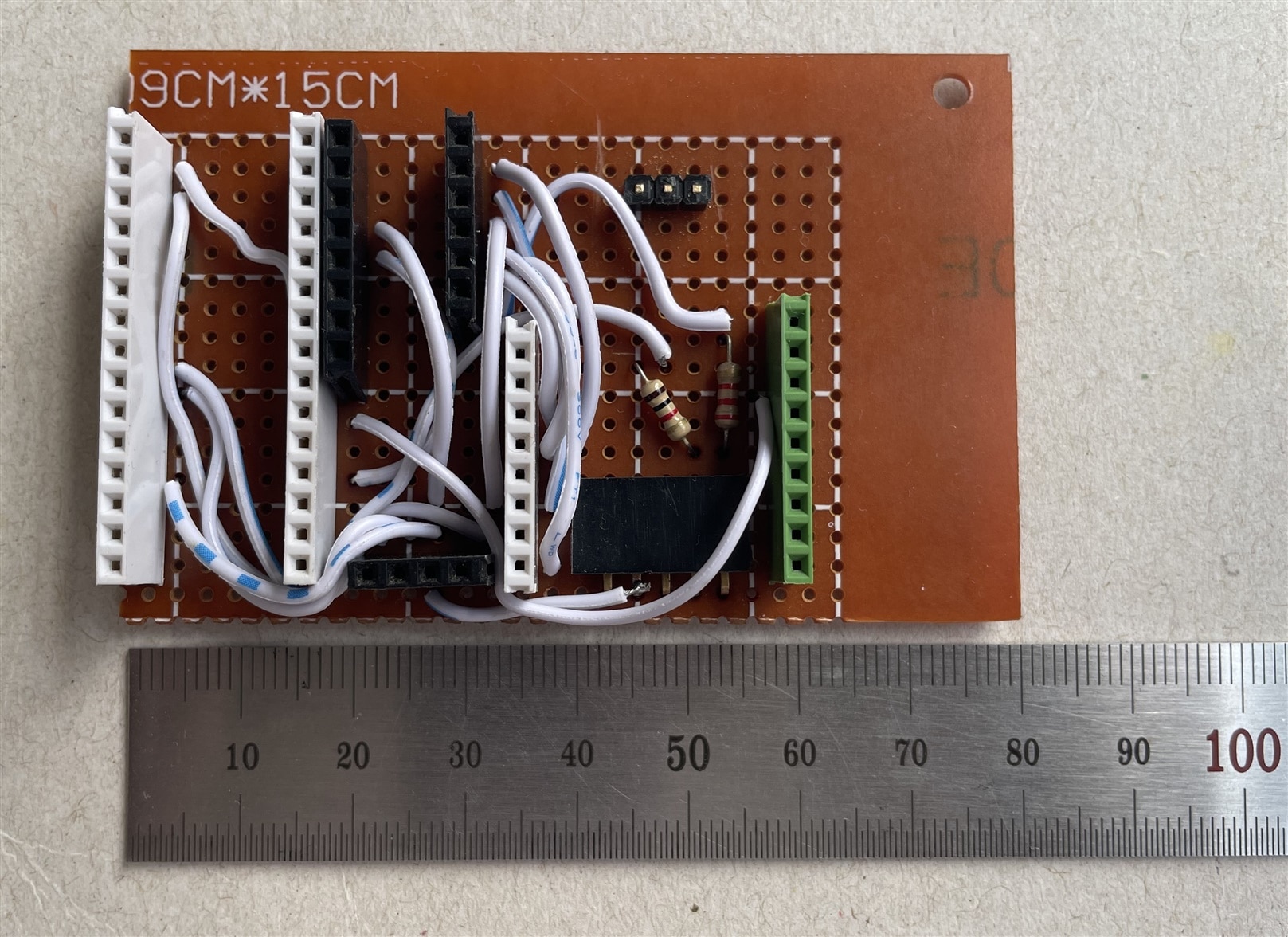
It is always a good idea to use pin headers without directly soldering any sensor module or microcontroller unit to a prototype PCB board. It will give us lots of advantages. We can easily remove the component from the PCB and reuse it in other circuits or breadboards. If we need to change the connection or the component itself we can easily do it without desoldering. Though using pin-headers slightly increase the size of the circuit vertically. I used female pin headers for every component I used in the device.
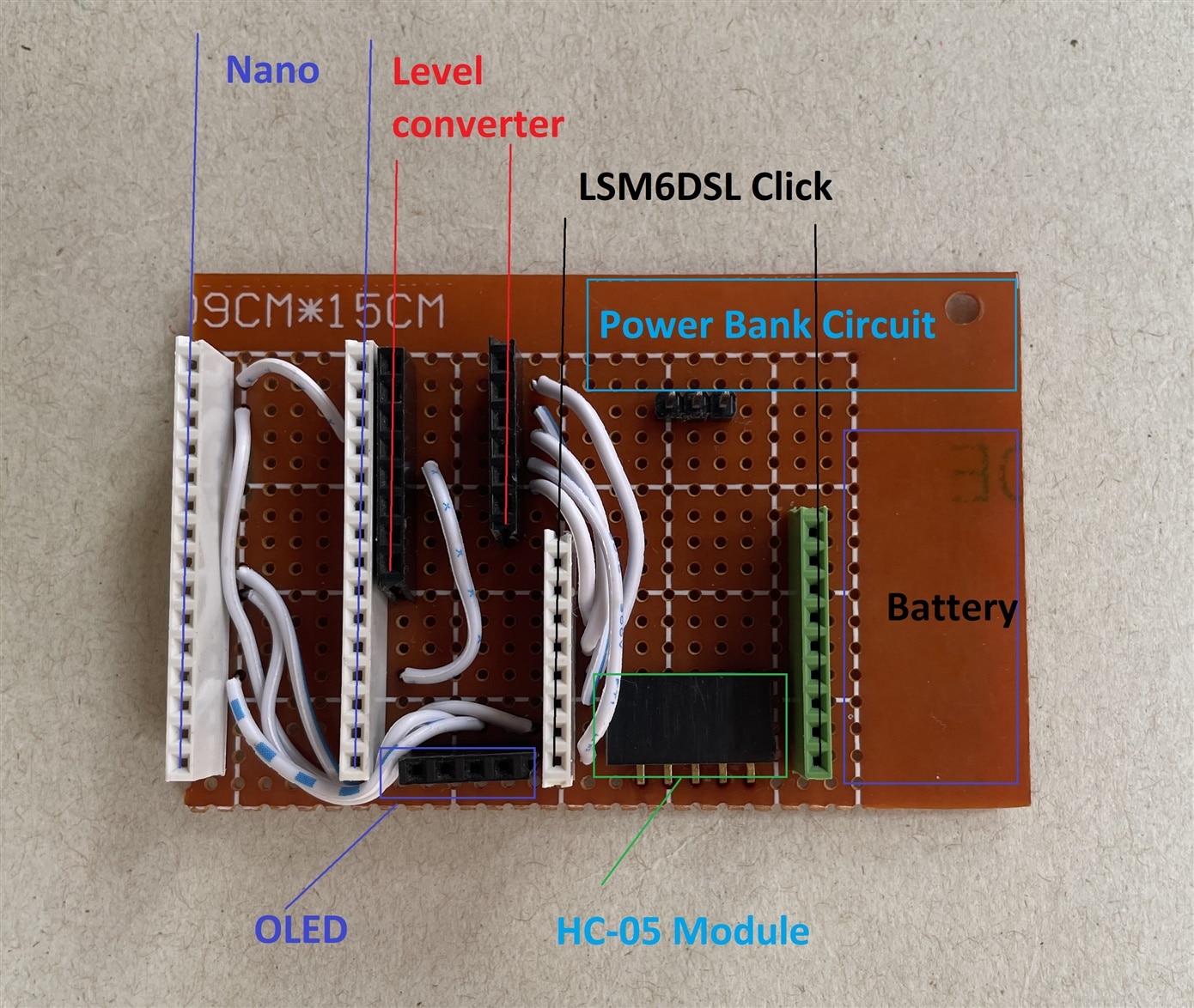
For size constrain I placed the Bluetooth module below the LSM6DSL click and the logic level converter below the OLED display. I followed the schematic provided earlier for making the connection using the white jumper wires shown in the above image.
It looks like the photo below after placing the HC-05 module and the logic level converter.
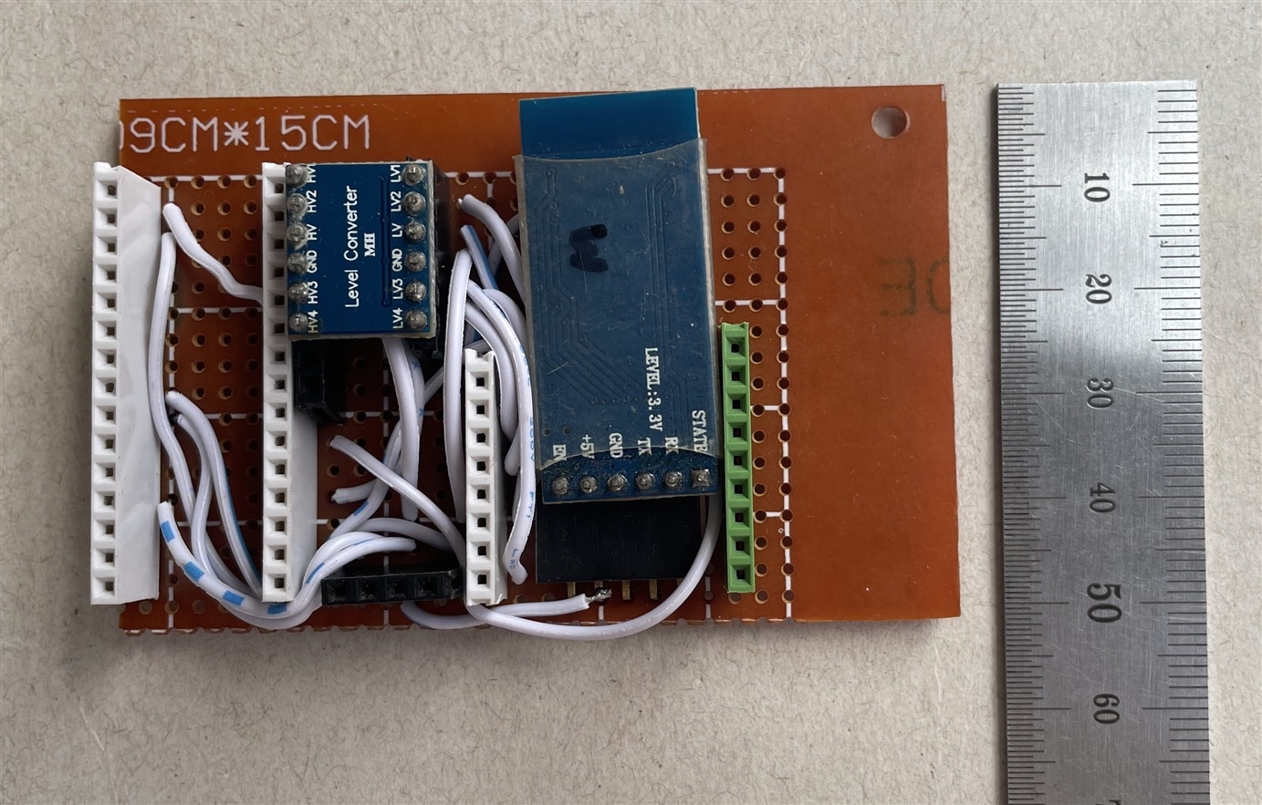
After placing the top components it looks like the below image. Still battery and the power bank circuit are not added.
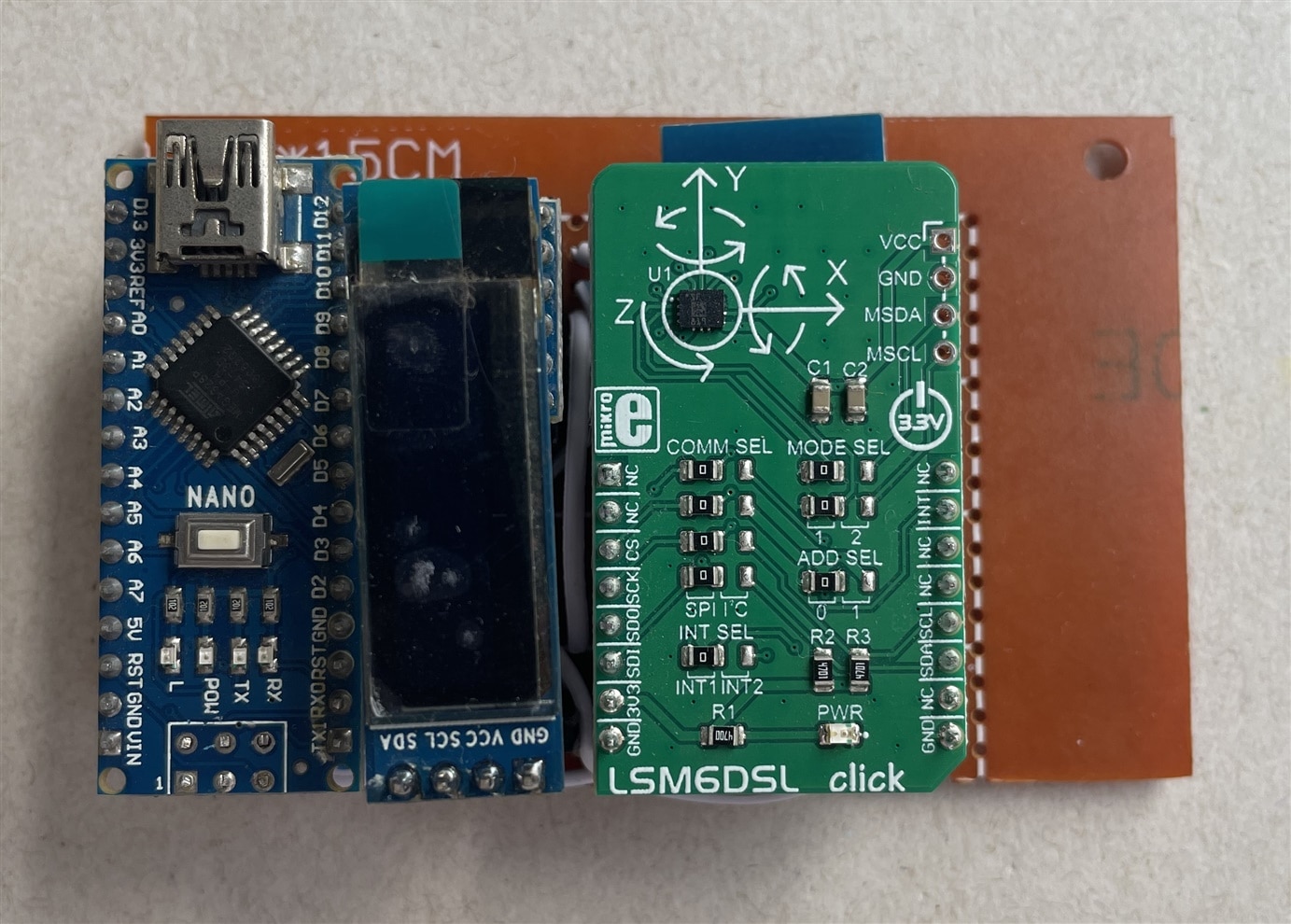
After placing the battery and the charger circuit the final wearable looks as the following image.
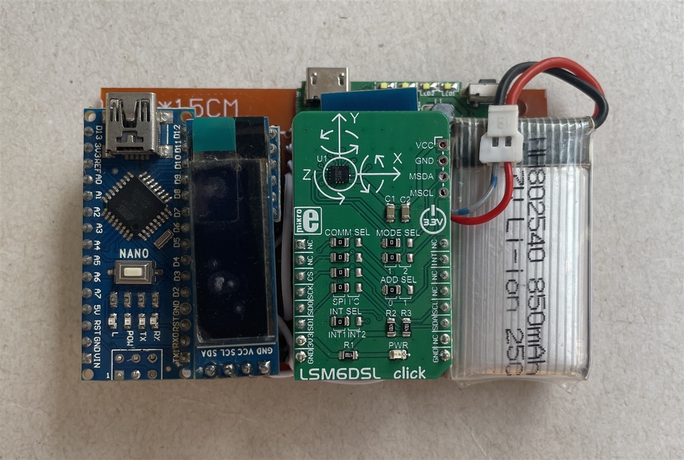
Configuring HC-05 Module
We are going to transmit data from one device through an HC-05 module to another device. The receiving device will also use an HC-05 module for receiving data from the transmitting device through Bluetooth. So, transmitting HC-05 will work as a master device and the receiving HC-05 will work as a slave device. But by default HC-05 is configured to work as a slave device. The good thing is that we can change the mode of HC-05 using AT command. So, before using the device we need to configure the transmitter module as a master device, and at the same time, we will configure it to bind with the slave directly using the MAC address of the slave device. For configuring the modules either we can use a USB TTL converter module or the Arduino to connect the Bluetooth module to the PC for sending the AT command.
We will connect the slave device first. For the slave device, we just need to note down the device's unique address and notice the baud rate.
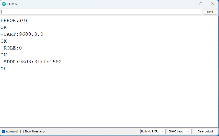
Then we will configure another module in master mode, bind it with the slave address and change the baud rate if it is not similar to the salve baud rate. Both master and slave must have set for same baud rate for successful Bluetooth communication.
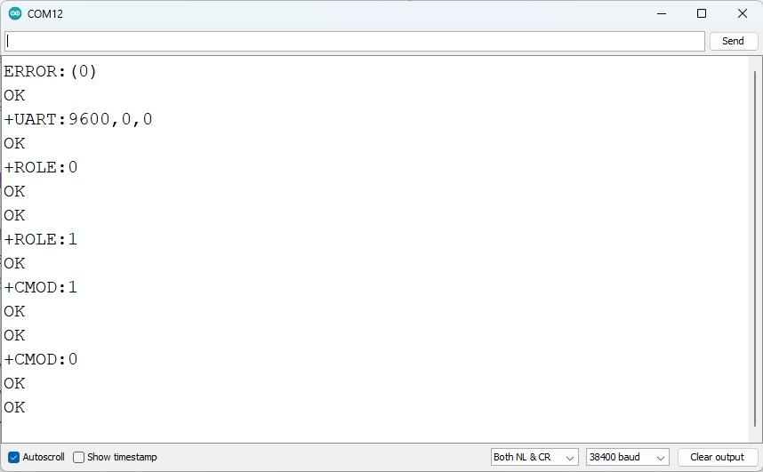
The configuration procedure is nicely explained and demonstrated in the following tutorial.
Follow the guidelines to configure your Bluetooth modules accordingly.
Programming (giving life to the device)
We can divide the program into several parts. These are single-tap detection, double-tap detection, free-fall detection, step count, sleep tracking, timekeeping, display information, and sending the information to the main unit. For performing most of the tasks we will use the LSM6DSL sensor. This sensor contains 3-axis digital accelerometer and 3-axis digital gyroscope. Accelerometer data is used for single tap, double tap, free fall, and step detection. Gyroscope data can be used for sleep tracking. Without sleep tracking, all other activity can be detected using the built-in function provided by the library. The library is available here. The details are discussed in the previous blog.
For sleep tracking, I used the code provided in this blog. I just modified some parts of the code to work with the LSM6DSL data. Here is the modified code for sleep tracking. The code is capable to detect light sleep as well as deep sleep.
void sleep_tracking(){
  int32_t gyroscope[3];
  AccGyr.Get_G_Axes(gyroscope);
  //without movement gyroscope value is in between -999 to 999 for all three dimension
  x = gyroscope[0]/10;
  y = gyroscope[1]/10;
  z = gyroscope[2]/10;
  if (activate == 0){ // first sleep confirmation
    if ((x<=99 || x>=-99) && (y<=99 || y>=-99) && (z<=99 || z>=-99)) {
    sleep_timer_start = millis()/1000-sleep_timer_end;
    if (sleep_timer_start == 300){
      activate = 1;
      }
    }
  if ((x>=99 || x<=-99) || (y>=99 || y<=-99) || (z>=99 || z<=-99)){
    sleep_timer_end =(millis()/1000);
    }
  }

  if (activate == 1){ // sleeping mode
    light_sleep = (millis()/1000)-sleep_timer_end;

    if (interrupt == 0){
      if (light_sleep >= 4200){
        if (interrupt_for_deep_sleep > 4200){
          if (light_sleep - interrupt_sleep_timer >= 600){
            deep_sleep = light_sleep - interrupt_for_deep_sleep;
            }
          }
        }
      }
    light_sleep = light_sleep - deep_sleep;

    if ((x>=99 || x<=-99) || (y>=99 || y<=-99) || (z>=99 || z<=-99)){
      interrupt_sleep_timer = (millis()/1000)-sleep_timer_end;
      interrupt_for_deep_sleep = light_sleep;
      interrupt =interrupt+1;
      delay(8000);
      }

    if ((millis()/1000)- sleep_timer_end -interrupt_sleep_timer > 300) {
      interrupt =0;
      }

    if ((millis()/1000)- sleep_timer_end - interrupt_sleep_timer <= 300){
      if (interrupt >=5){
        sleep_timer_end =(millis()/1000);
        if (light_sleep >= 900){ // second sleep confirmation
          total_light_sleep = total_light_sleep + light_sleep;
          total_deep_sleep = total_deep_sleep + deep_sleep;
          total_sleep = total_light_sleep + total_deep_sleep; }
          activate =0;
          interrupt =0;
          deep_sleep= 0;
          light_sleep= 0;
          interrupt_sleep_timer=0;
          interrupt_for_deep_sleep=0;
       }
     }
   }

   stage_sleep_time = light_sleep + deep_sleep;
   if (stage_sleep_time >= 5400){
     sleep_timer_end =(millis()/1000);
     total_light_sleep = total_light_sleep + light_sleep;
     total_deep_sleep = total_deep_sleep + deep_sleep;
     total_sleep = total_light_sleep + total_deep_sleep;
     activate =0;
     interrupt =0;
     deep_sleep= 0;
     light_sleep= 0;
     interrupt_sleep_timer=0;
     interrupt_for_deep_sleep=0;
   }
}
For tracking time I used Arduino Time Library by Paul Stoffregen. The library is available here. I didn't use any RTC for timekeeping because it does not require very precise time. Arduino-generated time is ok for the project.
For interfacing the OLED display I used the Adafruit OLED SSD1306 library. This library works fine for 128x32 OLED displays. The library is available here.
For transmitting data using HC-05 Arduino's built-in serial library is enough.
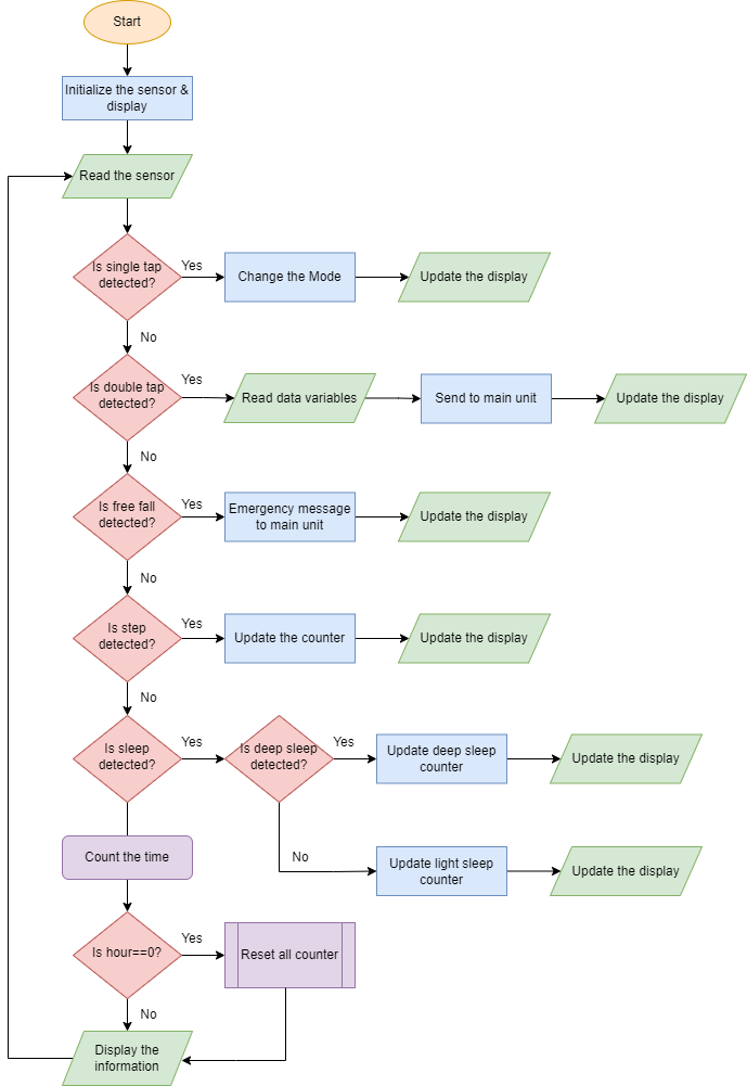
The full algorithm of the firmware code is provided below.
The full source code for the wearable unit is given below.
//Include libraries
#include <SPI.h>
#include <LSM6DSLSensor.h>
#include <TimeLib.h>
#include <Wire.h>
#include <Adafruit_GFX.h>
#include <Adafruit_SSD1306.h>

#define CS_PIN 8
#define SCREEN_WIDTH 128 // OLED display width, in pixels
#define SCREEN_HEIGHT 32 // OLED display height, in pixels
#define OLED_RESET     -1 // Reset pin # (or -1 if sharing Arduino reset pin)
#define SCREEN_ADDRESS 0x3C

// Components.
LSM6DSLSensor AccGyr(&SPI, CS_PIN);
Adafruit_SSD1306 display(SCREEN_WIDTH, SCREEN_HEIGHT, &Wire, OLED_RESET);


//Interrupts.
volatile int mems_event = 0;

uint32_t previous_tick = 0;
uint32_t current_tick = 0;
uint16_t step_count = 0;
char report[256];

int display_mode = 0;

void INT1Event_cb();

///variable sleep
long timer = 0;
long sleep_timer_start, sleep_timer_end,sleep_timer_end2;
float x,y,z;
int activate, interrupt, stage_sleep_time, interrupt_sleep_timer,
interrupt_for_deep_sleep, total_sleep, total_deep_sleep,
total_light_sleep, deep_sleep, light_sleep, interrupt_timer=0;

void setup() {
  Serial.begin(9600);
  //Initialize I2C bus.
  SPI.begin();
  //Interrupts.
  attachInterrupt(INT1, INT1Event_cb, RISING);
  // Initlialize Components.
  AccGyr.begin();
  AccGyr.Enable_X();
  AccGyr.Enable_G(); //enable gyroscope for sleep count
  // Enable Pedometer.
  AccGyr.Enable_Pedometer();
  // Enable Free Fall Detection.
  AccGyr.Enable_Free_Fall_Detection();
  // Enable Double Tap Detection.
  AccGyr.Enable_Double_Tap_Detection();
  // Enable Single Tap Detection.
  AccGyr.Enable_Single_Tap_Detection();
  previous_tick = millis();
  setTime(12,20,30,14,11,22);

  if(!display.begin(SSD1306_SWITCHCAPVCC, SCREEN_ADDRESS)) {
    //Serial.println(F("SSD1306 allocation failed"));
    for(;;); // Don't proceed, loop forever
  }
  // Show initial display buffer contents on the screen --
  // the library initializes this with an Adafruit splash screen.
  display.display();
  delay(2000); // Pause for 2 seconds
  // Clear the buffer
  display.clearDisplay();
  // Draw a single pixel in white
  display.drawPixel(10, 10, SSD1306_WHITE);
  // Show the display buffer on the screen. You MUST call display() after
  // drawing commands to make them visible on screen!
  display.display();
  delay(2000);
}

void loop() {
  if (mems_event)
  {
    mems_event = 0;
    LSM6DSL_Event_Status_t status;
    AccGyr.Get_Event_Status(&status);

    if (status.TapStatus)
    {
      // change the mode of the display.
      //Serial.println("Single Tap Detected!");
      display_mode++;
      display_time();
      if(display_mode>3) display_mode = 0;
    }

    else if (status.DoubleTapStatus)
    {
      // send data to main unit through bluetooth.
      //Serial.println("Double Tap Detected!");
      send_to_master(step_count, light_sleep, deep_sleep);
      display.clearDisplay(); //clears display
      display.setTextColor(SSD1306_WHITE); //sets color to white
      display.setTextSize(2); //sets text size to 2
      display.setCursor(0, 0); //change cursor to second row
      display.print("Data Sent");
      display.display(); //print to display
      delay(2000);
    }

    else if (status.FreeFallStatus)
    {
      // send fall notification through bluetooth.
      Serial.println("Fall");
      display.clearDisplay(); //clears display
      display.setTextColor(SSD1306_WHITE); //sets color to white
      display.setTextSize(2); //sets text size to 2
      display.setCursor(0, 0); //change cursor to second row
      display.print("Alert Sent");
      display.display(); //print to display
      delay(3000);
    }

    else if (status.StepStatus)
    {
      // New step detected, so print the step counter
      AccGyr.Get_Step_Counter(&step_count);
      snprintf(report, sizeof(report), "Step counter: %d", step_count);
      //Serial.println(report);
    }
  }

  // Print the step counter in any case every 3000 ms
  current_tick = millis();
  if((current_tick - previous_tick) >= 3000)
  {
    AccGyr.Get_Step_Counter(&step_count);
    snprintf(report, sizeof(report), "Step counter: %d", step_count);
    //Serial.println(report);
    previous_tick = millis();
  }

  if (timeStatus()!= timeNotSet) {
    display_time();
  }

  if(millis() - timer > 1000){
  sleep_tracking();
  timer = millis();
  }
}

void INT1Event_cb()
{
  mems_event = 1;
}


void display_time(){
  display.clearDisplay(); //clears display
  display.setTextColor(SSD1306_WHITE); //sets color to white
  display.setTextSize(2); //sets text size to 2
  display.setCursor(0, 0); //change cursor to second row
  print2digits(hour()); //retrieve hours
  display.print(":");
  print2digits(minute()); //retrieve minutes
  display.print(":");
  print2digits(second()); //retrieve seconds
  display.setCursor(0, 18); //change cursor to second row
  if(display_mode == 0){
    display.print("Steps: ");
    display.print(step_count);
  }
  if(display_mode == 1){
    display.print("Dst: ");
    display.print(step_count*0.3048);
    display.print(" M");
  }
  else if(display_mode == 2){
    display.print("DSL: ");
    display.print(deep_sleep);
    display.print(" H");
  }
  else if(display_mode == 3){
    display.print("LSL: ");
    display.print(light_sleep);
    display.print(" H");
  }
  display.display(); //print to display
  delay(10);
}

void print2digits(int number) {
  if (number < 10) {
    display.print("0"); // print a 0 before if the number is < than 10
  }
  display.print(number);
}

//send comma seperated value to the main unit
void send_to_master(int steps, int light_sleep, int deep_sleep){
  String message = "";
  message += steps;
  message += ",";
  message += light_sleep;
  message += ",";
  message += deep_sleep;
  Serial.println(message);
}

void sleep_tracking(){
  int32_t gyroscope[3];
  AccGyr.Get_G_Axes(gyroscope);
  //without movement gyroscope value is in between -999 to 999 for all three dimension
  x = gyroscope[0]/10;
  y = gyroscope[1]/10;
  z = gyroscope[2]/10;
  if (activate == 0){ // first sleep confirmation
    if ((x<=99 || x>=-99) && (y<=99 || y>=-99) && (z<=99 || z>=-99)) {
    sleep_timer_start = millis()/1000-sleep_timer_end;
    if (sleep_timer_start == 300){
      activate = 1;
      }
    }
  if ((x>=99 || x<=-99) || (y>=99 || y<=-99) || (z>=99 || z<=-99)){
    sleep_timer_end =(millis()/1000);
    }
  }

  if (activate == 1){ // sleeping mode
    light_sleep = (millis()/1000)-sleep_timer_end;

    if (interrupt == 0){
      if (light_sleep >= 4200){
        if (interrupt_for_deep_sleep > 4200){
          if (light_sleep - interrupt_sleep_timer >= 600){
            deep_sleep = light_sleep - interrupt_for_deep_sleep;
            }
          }
        }
      }
    light_sleep = light_sleep - deep_sleep;

    if ((x>=99 || x<=-99) || (y>=99 || y<=-99) || (z>=99 || z<=-99)){
      interrupt_sleep_timer = (millis()/1000)-sleep_timer_end;
      interrupt_for_deep_sleep = light_sleep;
      interrupt =interrupt+1;
      delay(8000);
      }

    if ((millis()/1000)- sleep_timer_end -interrupt_sleep_timer > 300) {
      interrupt =0;
      }

    if ((millis()/1000)- sleep_timer_end - interrupt_sleep_timer <= 300){
      if (interrupt >=5){
        sleep_timer_end =(millis()/1000);
        if (light_sleep >= 900){ // second sleep confirmation
          total_light_sleep = total_light_sleep + light_sleep;
          total_deep_sleep = total_deep_sleep + deep_sleep;
          total_sleep = total_light_sleep + total_deep_sleep; }
          activate =0;
          interrupt =0;
          deep_sleep= 0;
          light_sleep= 0;
          interrupt_sleep_timer=0;
          interrupt_for_deep_sleep=0;
       }
     }
   }

   stage_sleep_time = light_sleep + deep_sleep;
   if (stage_sleep_time >= 5400){
     sleep_timer_end =(millis()/1000);
     total_light_sleep = total_light_sleep + light_sleep;
     total_deep_sleep = total_deep_sleep + deep_sleep;
     total_sleep = total_light_sleep + total_deep_sleep;
     activate =0;
     interrupt =0;
     deep_sleep= 0;
     light_sleep= 0;
     interrupt_sleep_timer=0;
     interrupt_for_deep_sleep=0;
   }
}
Operational Block Diagram
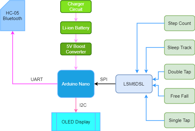
The following block diagram illustrates the interconnection and operation of different hardware units.
Operational Video
Here I added a short video for demonstrating the working of my wearable unit.
Conclusion
In my next blog, I am going to finish my main unit.

