Challenger - ZMOD4510 - Outdoor Air Quality Sensor
Hello element14 Family,
In order to correctly fit the board into the case properly, I first soldered pullup resistors onto the OLED display itself. After that, I assembled all the parts at my workstation.
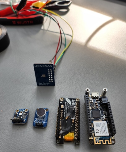
From Left to Right:
Si7021 Temperature & Humidity Sensor, MAX4466 Electret Microphone (Set To 25x Gain), OLED FeatherWing, Feather M0 WiFi Board – with the ZMOD4510 in the background!
Once the SLA-printed structure was complete, I had to give it a nice alcohol bath to make sure no harmful resin remained on it. There is an excellent explainer available from the manufacturer if you want to know more about it.
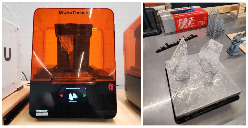
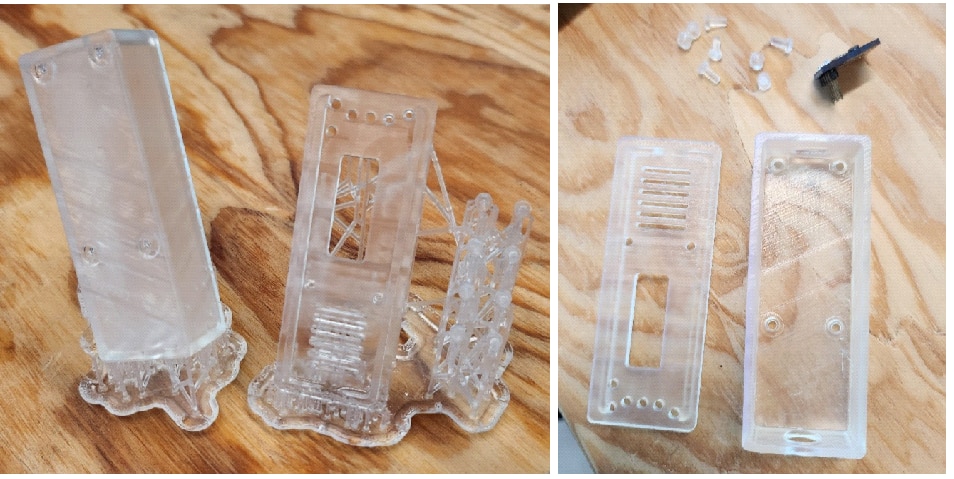
followed by a curing process of 30 minutes and breakout of the support structures (which is always fun and scary at the same time)
Finally, I attached the thin wires onto the MAX4466 Electret Microphone and the Si7021 Temperature and Humidity Sensor at my workstation. I can now choose a Feather M0 LoRa board or a Feather M0 WiFi board to use for the sample.
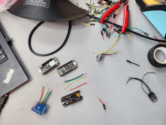
Color Code: RED – PWR, BLACK – GND, YELLOW – SCL, GREEN - SDA
I just decided to go ahead with the WiFi board for now to maybe try and demonstrate the cloud features. Since I2C is a shared bus, I connected the PWR, GND, SCL and SDA from the Si7021 and ZMOD4510 together, along with the PWR and GND from the MAX4466 Electret Microphone. Then, I connected the common PWR wire to 3.3V, the GND wire to GND, the SCL wire to Pin 21 and SDA wire to Pin 20 on the Feather M0. Finally, I connected the OUT of MAX4466 to an analog pin (A5) and inserted the OLED feather wing on to the base pins.
To perhaps try and demonstrate the cloud functionalities, I've just decided to move forward with the WiFi board for the time being. I linked the PWR, GND, SCL, and SDA from the Si7021, ZMOD4510, as well as the PWR and GND from the MAX4466 Electret Microphone together since I2C is a shared bus.
After that, I wired the Feather M0 by connecting the common PWR wire to 3.3V, the GND wire to GND, the SCL wire to Pin 21, and the SDA wire to Pin 20. Finally, I attached the OLED feather wing to the base pins, while connecting the MAX4466's OUT pin to analog pin (A5) on the Feather M0.
The final wired chump looks something like this:
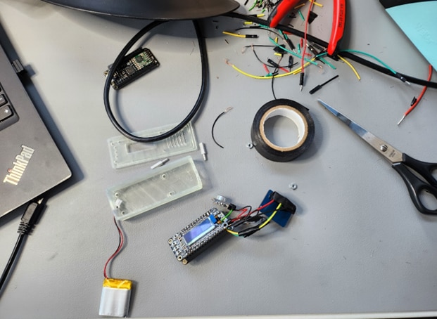
Now, I tried to test the access to the sensor using the OAQ 1st Gen Sensor example, however, I was unable to see any logs on the serial console. I noticed that there was no particular logging information initially available and I added additional logs, which were also not displayed on the console.
I then tried to use the OAQ 1st Gen Sensor example to verify access to the sensor, but I was unable to view any logs on the serial console. I added more logs after realizing that there was initially no specific logging information accessible, however those logs were also not shown on the console.
However, after flashing, the OAQ 2nd Gen Sensor sample worked perfectly! I therefore asked the Renesas Support Team for their opinion, albeit their response is pretty understandable:
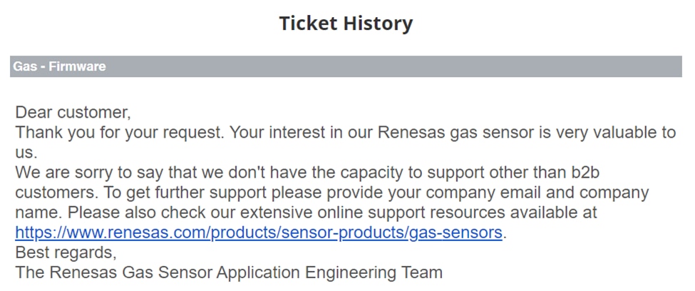
As I already have the Si7021 attached, I can move on to the OAQ 2nd Gen example for the time being (since it is also an example of ultra low power measurement) and implement algorithmic compensation using the sensor's recorded values for temperature and humidity.
Then, using the Adafruit SSD1306 example as a model, I created some code to test the basic functionality:
/* Includes For Adafruit OLED Featherwing */
#include <SPI.h>
#include <Wire.h>
#include <Adafruit_GFX.h>
#include <Adafruit_SSD1306.h>

/* OLED Display Width (Pixels) */
#define SCREEN_WIDTH   128
/* OLED Display Heighth (Pixels) */
#define SCREEN_HEIGHT  32
/* OLED Reset Pin (-1 If Sharing Arduino Reset Pin) */
#define OLED_RESET     -1
/* OLED I2C Address (Datasheet: 0x3C for 128x32) */
#define SCREEN_ADDRESS 0x3C

/* OLED Display */
Adafruit_SSD1306 display(SCREEN_WIDTH, SCREEN_HEIGHT, &Wire, OLED_RESET);

void setup()
{
    /* Initialize The Serial Port */
    Serial.begin(9600);

    /* Initialize The OLED Display */
    /* SSD1306_SWITCHCAPVCC - Generate Display Voltage From 3.3V Internally */
    if(!display.begin(SSD1306_SWITCHCAPVCC, SCREEN_ADDRESS))
    {
        Serial.println(F("SSD1306 OLED Display Error"));
        for(;;); // Don't Proceed, Loop Forever
    }

    display.clearDisplay();
    display.setTextSize(1);      // Normal 1:1 Pixel Scale
    display.setTextColor(SSD1306_WHITE); // Draw White Text
    display.setCursor(0, 0);     // Start At Top-left Corner
    display.cp437(true);         // Use Full 256 Char 'Code Page 437' Font

    /* Print A Welcome Message */
    display.println(F("Welcome To"));
    display.println(F("element14"));
    display.println(F("Summer of Sensors"));
    display.println(F("Design Challenge!\n"));
    display.display();
    delay(5000);
    display.clearDisplay();
    display.setTextColor(SSD1306_WHITE);
    display.setCursor(0, 10);
    display.println(F("In The Air Tonight..."));
    display.display();
    delay(100);
}

void loop() {
}
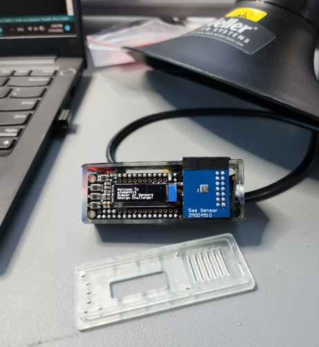
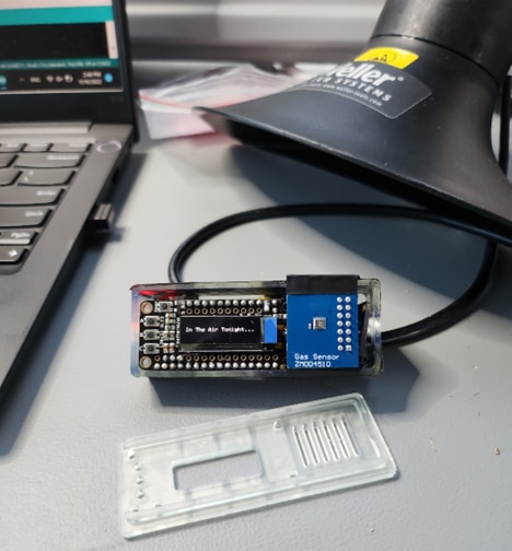
Next, I will pack the components into the case integrate a display which provides information on the current environment and exposure level.
Until then, Happy Cleaning!
Next Blog Series: Summer of Sensors Design Challenge - In The Air Tonight – Blog #5 (System Integration)
