Hello everyone. I welcome you to forth from five blog about VEML3328. This blog I wrote as my last-minute entry to the Summer of Sensors Competition in category Exploration stations. It is forth of five blogs. I decided to start and complete this project today. I started approx. 6 hours before deadline and now I have half hour to post last two blogs.
Project
As I mentioned in previous blog, I decided to use STM32G0 microcontroller for interfacing with VEML3328 color sensor. For project I used very cool STM32G0 MCU in SOIC8 package with only 8 pins (with subtraction powering pins, SWD pins and reset pins it decreases even more).
Working with this MCU in STM32CubeIDE looks as follows. Pretty funny. :D
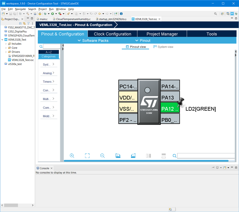
To this project I implemented library mentioned in previous blog post. For displaying data, I used I2C OLED display (which in fact I also received as part of my recent Project14 competition reward). I write application which configures sensor according to my parameters and then display outputs for every channel (Red, Green, Blue, Clear and IfraRed) using progress bars on the display. Most of the time I spend with getting display working. Work with sensor was quite a seamless. Good part is that I did not noticed any bug when working with my VEML3328 library written in hurry approx. 4 hours ago and it worked out of the box. I think it is because I have written several libraries.
Connection
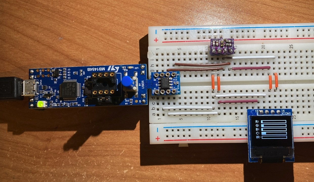
Both display and sensor are connected using shared I2C bus. On breadboard it looks as follows.
First output
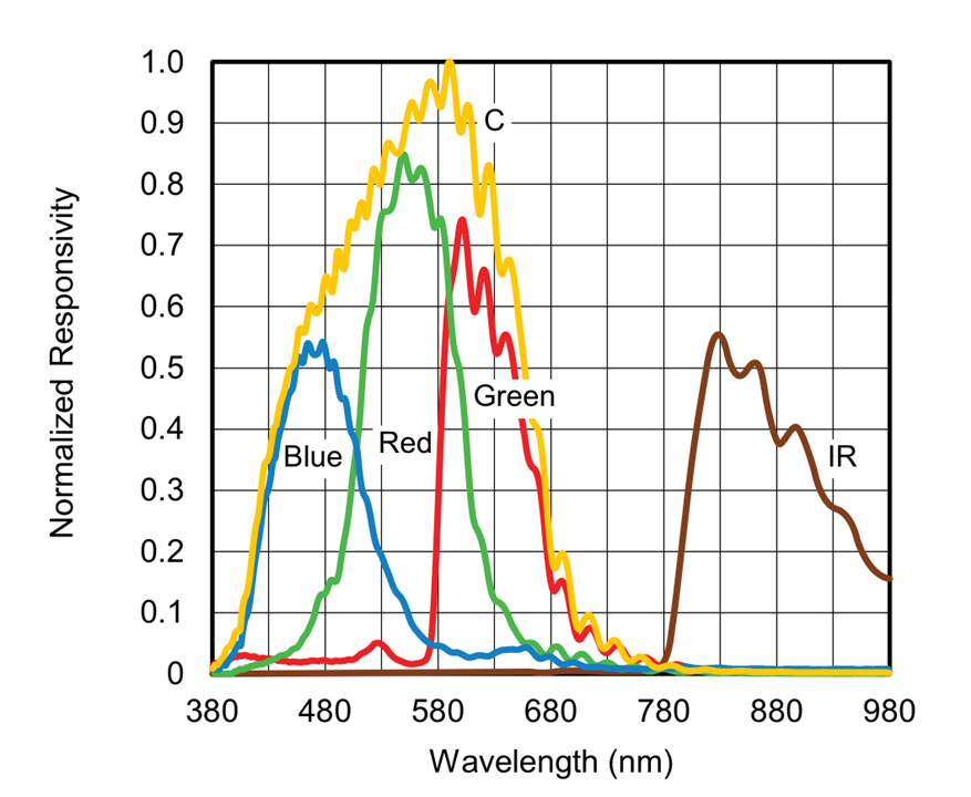
First output you can see on previous picture. It is captured by iPhone with flashlight enabled. As you can see except IR progress bar all shows some non-zero values. Flashlight is naturaly white color, so it contains all segments (R, G, B). From output we can see that sensor is more sensitive on green channel rather than on red and blue. Similarly values on Clear are very high because Clear channel is sensitive to all colors. These findings correspond with datasheet. Datasheet mention following sensitivities for channels.
Testing DIY colour filter
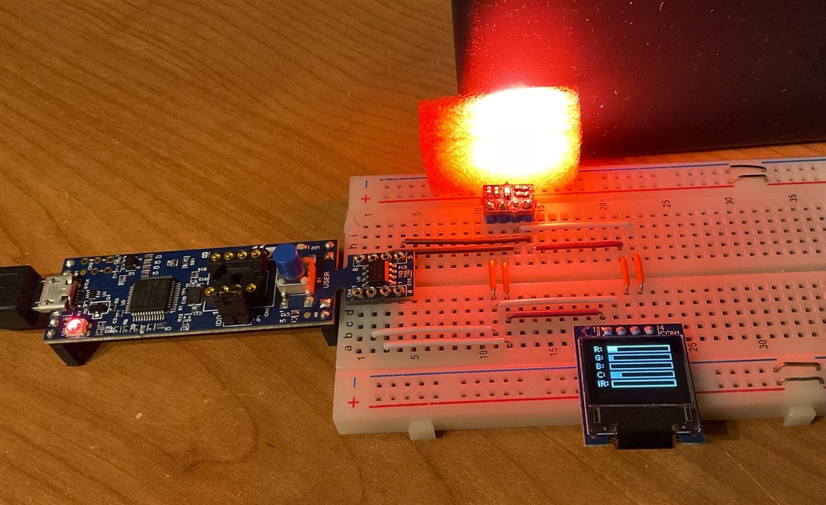
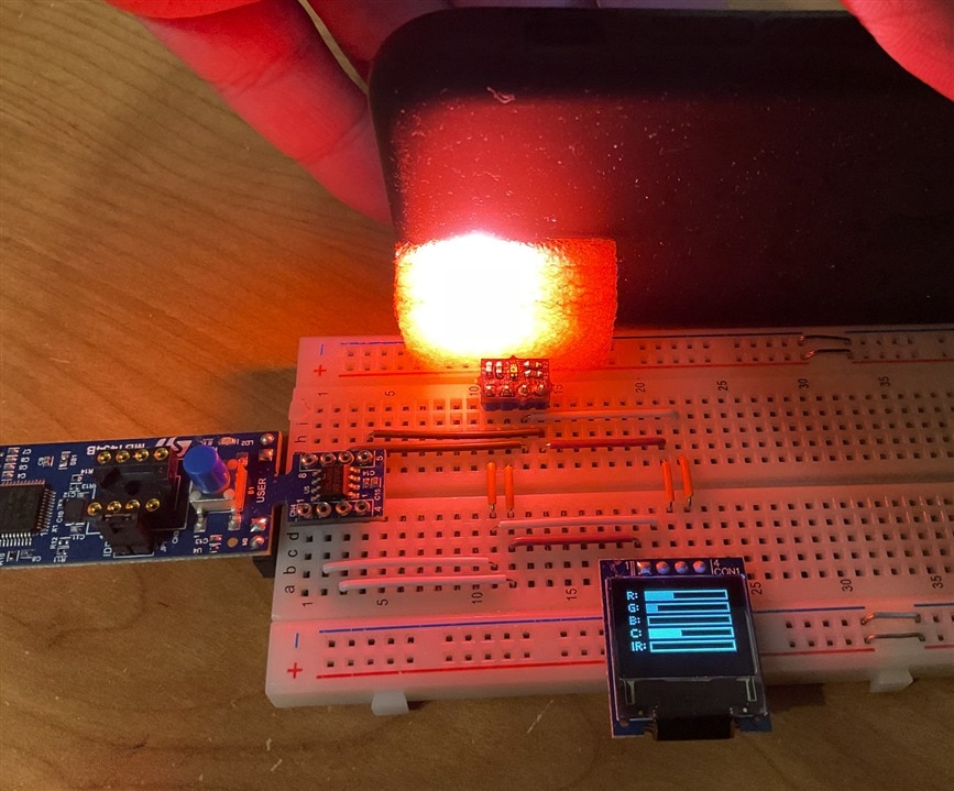
For further experiments I use red antistatic foam and flashlight at the back side of it. As you can see sensor now sensed much more red color which make sense, because it is backlighted by red light.
With this setup I tested changing several parameters.
Digital Gain
The first parameter is digital gaing or DG. In datasheet it is referred as DG and it never explain what DG abbreviation means, but I think it is some kind of digital gain. Possible values are x1, x2 and x4. I tried x4 and measured values was really higher but not four times. I gues about 2 to 3 times. Maybe there were slightly difference by caused by position of the light.
Analog gain
Second parameter which I tried was enabling analog gain also. Possible values are x1/2, x1, x2, x4. I tested it with configuration that both analog and digital gains were set to 4. Output very soon reached maximum possible value (65535 because resolution sensor is 16-bit).
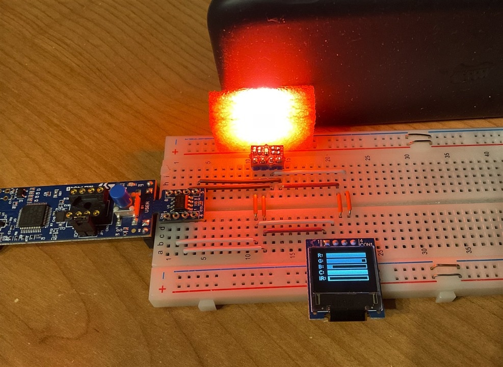
As you can see sensor can with good configuration fully utilize its scale.
With both gains at maximum values became instable and there were lot of noise (which was visible on slow display).
Integration Time
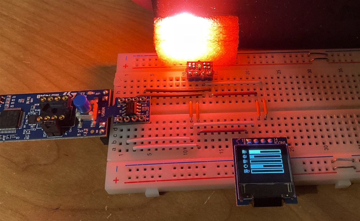
Then I disabled both gains and instead adjusted changing integration time. Possible values are 50ms, 100ms, 200ms and 400ms. I tested 200ms. Values were higher than in case od default 50ms, but less sensitive to noise.
Disabling unused channels
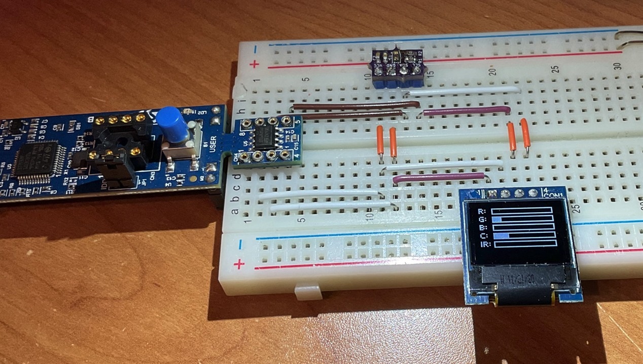
Last experimenting was feature allowing disabling some channels. After enabled this feature I was receiving only G, C and IR values from the sensor exactly as expected.
This is all. I have no time, so I go post this blog. In this blog you have seen my project and some outputs from the sensor. In last blog I will summarize my work.
Next blog: VEML3328 Last-Minute Entry: Blog #5 Summary

