


1. About Profet+2 12v Shield for Arduino Shield
The PROFET +2 Arduino Shield with BTS700x-1EPP can be controlled with general logic IO-Ports of a microcontroller. Either an Arduino Uno R3, the Arduino Due, the XMC 1100 Boot Kit or the more powerful XMC 4700 Relax Kit and XMC 4800 Relax Kit from Infineon can be used as the master. y. Each one is built by a vertical N-channel power MOSFET with charge pump. Due to the integrated charge pump the channels can be controlled by standard digital IOs (3.3 V and 5 V supported). All of them are single channel devices with a very small ON-state resistance (e.g. the BTS7002-1EPP with one 2.6 mΩ channel)
- With an integrated charge pump, internal protection features and a current feedback to the ADC of the microcontroller
- Supply voltage: functional range: 4.1 V - 28 V; nominal range: 3.1 V - 35 V
- Nominal current between 11 A per channel (BTS7008-1EPP) and 21 A (BTS7002-1EPP) per channel restricted due to the limited power dissipation of the PCB and the used PROFET
Diagnosis and protection function as well. That would be one of the versitile Driver of motors.
Wiring diagram
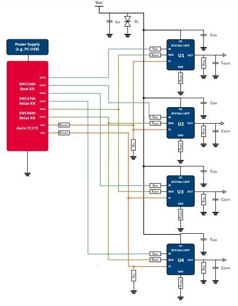
2. Use the PROFET+12
To use the PROFET +12 Arduino Shield the necessary control signals can be applied directly at the connectors. There is no need to use a microcontroller compatible with Arduino or XMC
1100 Boot Kit to get the PROFET +12 Arduino Shield into an application. The control pins are logic level inputs which can be driven by any other microcontroller or with logic level signals. Besides the supply voltage Vbat has to be provided to the Vbat connector. Here is the pin-out and the connectors.
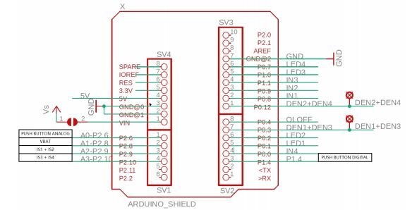
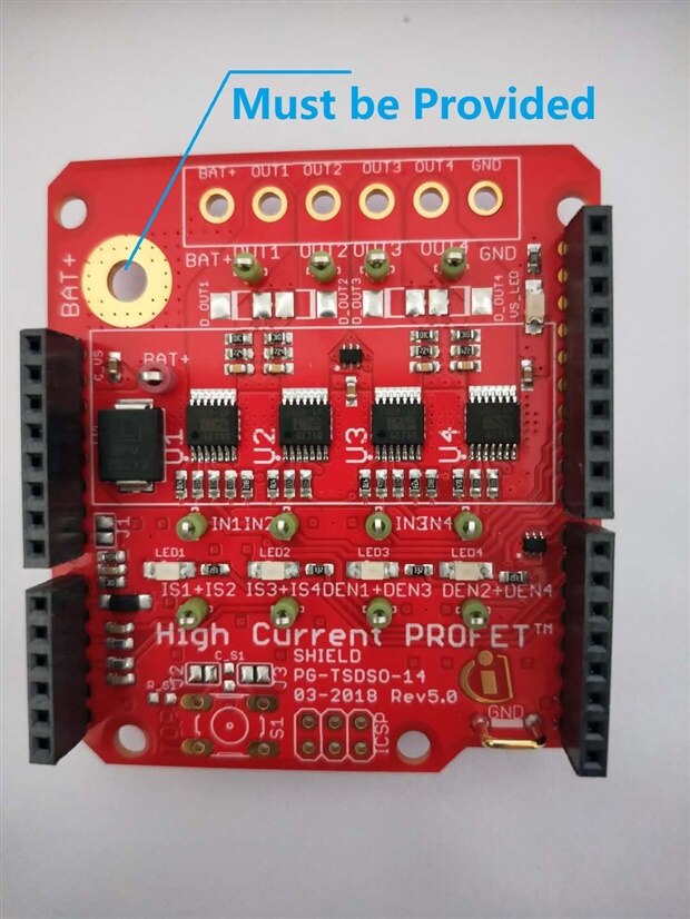
Detail introduction of pins, In this project, only one switch shall be used and highlighted.

One interesting part of the OpenLoad protection. For some loads, it may be necessary to check their availability without powering them up without creating a flash light by switching them on.
A small current (few milliamperes) is injected into the output, powerful enough to pull up the output if there is no load connected, but not powerful enough to activate the load in a distrubing manner. If the output voltage of a PROFET+2 12V becomes too high, drain-source voltage will be lower than VDS(OLOFF), and the PROFET will provide an open load signal IIS(OLOFF).
Another useful function is Diagnosis. The Diagnosis Enable (DENx) and the current sense (ISx) are conntected in a way, that you can only use 2 different BTS700x-1EPP at a time (U1+U3 or U2+U4). The current sense outputs of the devices U1 and U2 are connected by sharing one ADC input of the microcontroller (analog input A2). The same applies to the devices U3 and U4 which are connected to the analog input A3.
Since jumper J1 is not connected, the microcontroller board is powered by the USB port to the microcontroller to supply the device.
3. Arduino Library for Profet+2 and Basic Arduino Sketch for Profet+2
Even the arduino lib is provided by Infineon. That is called high-side-switch, find it and download. Here is sample arduino sketch using XMC1100.
/**
 * @file        high-side-switch.ino
 * @brief       High-Side-Switch Example for the Arduino form factor
 *
 *              This example shows the usage of the Arduino API.
 *              It covers all functions of the PROFET-Shield and shows how the functions are used.
 *              It can be deployed to the Arduino Uno or the XMC's with corresponding form factor.
 *
 * @copyright   Copyright (c) 2020 Infineon Technologies AG
 */
#include <Arduino.h>
#include <hss-board-arduino.hpp>


/**
 * Here we create an object of the High-Side-Switch-Board class with the Name HSS.
 * The constructor needs the used version of the PROFET.
 *
 * Available versions are:
 * - BTS7002
 * - BTS7004
 * - BTS7006
 * - BTS7008
 *
 * Make sure you chose the right one. Otherwise the diagnosis functions can may work incorrectly.
 */
HssBoardIno HSS = HssBoardIno(&BTS7002);


void setup()
{   /** Serial initialization */
    Serial.begin(115200);
    delay(2000);
    Serial.println("Serial initialized");


    /** Initialization of the High-Side-Switch-Board */
    HSS.init();
    delay(1000);
    Serial.println("High-Side-Switch is initialized");
}


void loop()
{
    int incomingSerial = 0;
    static int counter = 0;
    static int oldCounter = 0;


    float readAmps = 0.0;
    float batteryVoltage = 0.0;


    int switchStatus = 0;


    /**
     * This small if-case is checking for an user input.
     * To use this press the "+" symbol on your keyboard, this is equal to "43" in ASCII.
     */
    if(Serial.available() > 0){
        incomingSerial = Serial.read();


        if(incomingSerial == 43){
            counter++;
        }
    }


    /**
     * This if-case are used to show all functions of the board.
     * Depending on the value of the counter the board will do the following:
     *      - From 1 to 4:
     *          Switch on all four channels, one after the other starting with channel 1
     *          Also reads out the diagnostic channel of the corresponding channel
     *      - From 5 to 8:
     *          Switch off all four channels, one after the other starting with channel 1
     *          Also reads out the diagnostic channel of the corresponding channel
     *      - From 9 to 10:
     *          First turns on all channels at once
     *          Then turns off all channels at once
     *      - After that the counter will be reset and you can use the program again
     *
     * The status of the switch can be determined with the following table:
     *      || Diagnosis Status || Description                                                      ||
     *      ------------------------------------------------------------------------------------------
     *      ||          0       || NORMAL = Everything is working correctly                         ||
     *      ||          1       || OVERLOAD = Exceeded the board's current limit                    ||
     *      ||          2       || SHORT_TO_GND = Short the ground of the board                     ||
     *      ||          3       || OVERTEMPERATURE = Board got to hot                               ||
     *      ||          4       || SHORT_TO_VSS = Short to the Battery pad of the board             ||
     *      ||          5       || OPEN_LOAD = No load is connected                                 ||
     *      ||          6       || UNDER_LOAD = Not enough voltage/current to turn on the switch    ||
     *      ||          7       || INVERSE_CURRENT = Inverse current flows into the board           ||
     *
     * Please note: If you use the diagnosis function when the switch is off and no load is connected
     * the status will be SHORT_TO_GND, because this state is not clear because of the provided IS signal
     * of the board. Read more about this in the data sheet of the PROFET on page 40.
     */
    if(counter > 0 && counter < 5 && oldCounter != counter){
        HSS.switchHxOn(counter);
        Serial.print("Switched half bridge ");
        Serial.print(counter);
        Serial.println(" on");


        Serial.println("Reading the current and diagnosis status of this switch ...");
        readAmps = HSS.readIsx(counter);
        Serial.print("Current flowing through the switch: ");
        Serial.print(readAmps);Serial.println(" A");


        switchStatus = HSS.readDiagx(counter);
        Serial.print("Diagnosis status of the switch: ");
        Serial.println(switchStatus);


        batteryVoltage = HSS.readVss();
        Serial.print("Current battery voltage : ");
        Serial.print(batteryVoltage);Serial.println(" V\n");


        oldCounter = counter;
    }
    else if(counter > 4 && counter < 9 && oldCounter != counter){
        HSS.switchHxOff(counter - 4);
        Serial.print("Switched half bridge ");
        Serial.print(counter - 4);
        Serial.println(" off");


        Serial.println("Reading the current and diagnosis status of this switch ...");
        readAmps = HSS.readIsx(counter - 4);
        Serial.print("Current flowing through the switch: ");
        Serial.print(readAmps);Serial.println(" A");


        switchStatus = HSS.readDiagx(counter - 4);
        Serial.print("Diagnosis status of the switch: ");
        Serial.println(switchStatus);


        batteryVoltage = HSS.readVss();
        Serial.print("Current battery voltage : ");
        Serial.print(batteryVoltage);Serial.println(" V\n");


        oldCounter = counter;
    }
    else if(counter > 8 && counter < 11 && oldCounter != counter){
        if(counter == 9){
            Serial.println("\nTurn on all switches at once!");
            HSS.switchesHxOn(1,1,1,1);
            oldCounter = counter;
        }
        else if(counter == 10){
            Serial.println("\nTurn off all switches at once and reset counter!");
            HSS.switchesHxOff(1,1,1,1);
            oldCounter = counter;
            counter = 0;
        }
    }
}
4. Next to do.
Then , have fun with this easy-to-use High-Switch on the project.