


This week I spent most of the time finishing the program and put all together in the box. It’s a troubleshooting week, as many problems arise during assembly all components in the box.
At the start, I plan for Auto program to start and finished with one button. However, I realized that when you start crusher motor. You do not know when to stop because you don’t know how much time you need. Then I modified Auto program to stop when press start/stop button again for move to next state. EM valve will start to release EM and then start the Stir motor to mix all together for a specific time and stop.
Summary of Ports uses to control program.
Arduino Port
AUTO PROGRAM LED STATUS 0
MOTOR CRUSH LED STATUS 1
SERVO FOR EM LED STATUS 8
MOTOR STIR LED STATUS 9
WORKING LED STATUS 6
SERVO PORT 5
START/STOP SW 2
On the front panel, I had installed two more LEDs for future expansion. One for an indication of EM empty and one for waste bin full warning. I am not sure that have time to Implement, so I will freeze the code now to begin machine construction.
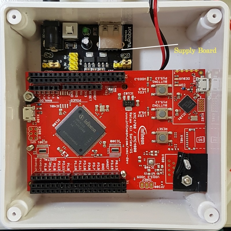
I had bought the box for electric cabinet and start to put all components together. For power supply, I will use 12 V adapter and 12 to 5 V/3.3V adapter board. This board causes me many problems. It’s very hot when supplying the current and burns. I changed the new one and it’s still very hot. It seems that these boards under spec. I bought them very cheap from internet. XMC4700 begin reset after the Servo move. I waste a lot of time to solve this and just found that the current is not enough. When I change for bigger supply, it solves the problem. But I need to change the supply board. The supply board shown in the picture needs to be changed.
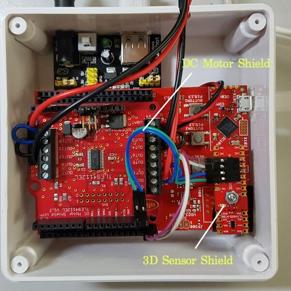
Next, install the DC Motor shield and 3D sensor shield on top of XMC4700 Relax kit. I use one screw to fix 3D sensor with XMC4700. OUT1,2 use for Crush Motor’s HighSide and OUT3, 4 use for Crush Motor’s LowSide. OUT9,10 use for Stir Motor’s HighSide and OUT11,12 use for Stir Motor’s LowSide.
On Front Panel, I installed LEDs, Start/Stop Switch and Knob control. There are 7 LEDs, one switch and Knob control as in the picture.
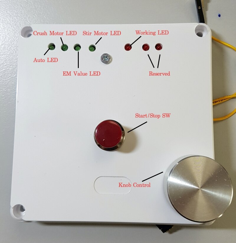
And at the back you will see the magnet at the end of the knob.
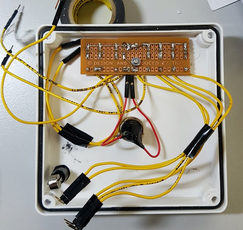
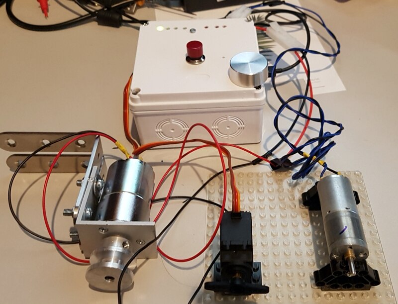
I used push button for start/stop switch. First I use interrupt for switch checking. But found a lot of problems according to switch debounce. I decided to change back to use normal switch checking in arduino loop. Motor and Servo connectors had been wired outside. Here is the finished control box.
As I said before, I found the program reset every time Servo is working. I think it’s the program bug and try to debug it. After spent one night, I found that because the power
supply is not enough to drive board and Servo. When I changed supply for more ampere, the problem solved. Please take this into consideration when you add more devices.
Two Motors use 12 V DC and there are no problems with current from adapter.
Below is the Video show how the controller works in Auto Mode and individual control for each device.
Next I will start to assembly the machine and will update it in the next blog.
