element14 Community
element14 Community
    Register Log In
  • Site
  • Search
  • Log In Register
  • About Us
  • Community Hub
    Community Hub
    • What's New on element14
    • Feedback and Support
    • Benefits of Membership
    • Personal Blogs
    • Members Area
    • Achievement Levels
  • Learn
    Learn
    • Ask an Expert
    • eBooks
    • element14 presents
    • Learning Center
    • Tech Spotlight
    • STEM Academy
    • Webinars, Training and Events
    • Learning Groups
  • Technologies
    Technologies
    • 3D Printing
    • FPGA
    • Industrial Automation
    • Internet of Things
    • Power & Energy
    • Sensors
    • Technology Groups
  • Challenges & Projects
    Challenges & Projects
    • Design Challenges
    • element14 presents Projects
    • Project14
    • Arduino Projects
    • Raspberry Pi Projects
    • Project Groups
  • Products
    Products
    • Arduino
    • Avnet Boards Community
    • Dev Tools
    • Manufacturers
    • Multicomp Pro
    • Product Groups
    • Raspberry Pi
    • RoadTests & Reviews
  • Store
    Store
    • Visit Your Store
    • Choose another store...
      • Europe
      •  Austria (German)
      •  Belgium (Dutch, French)
      •  Bulgaria (Bulgarian)
      •  Czech Republic (Czech)
      •  Denmark (Danish)
      •  Estonia (Estonian)
      •  Finland (Finnish)
      •  France (French)
      •  Germany (German)
      •  Hungary (Hungarian)
      •  Ireland
      •  Israel
      •  Italy (Italian)
      •  Latvia (Latvian)
      •  
      •  Lithuania (Lithuanian)
      •  Netherlands (Dutch)
      •  Norway (Norwegian)
      •  Poland (Polish)
      •  Portugal (Portuguese)
      •  Romania (Romanian)
      •  Russia (Russian)
      •  Slovakia (Slovak)
      •  Slovenia (Slovenian)
      •  Spain (Spanish)
      •  Sweden (Swedish)
      •  Switzerland(German, French)
      •  Turkey (Turkish)
      •  United Kingdom
      • Asia Pacific
      •  Australia
      •  China
      •  Hong Kong
      •  India
      •  Korea (Korean)
      •  Malaysia
      •  New Zealand
      •  Philippines
      •  Singapore
      •  Taiwan
      •  Thailand (Thai)
      • Americas
      •  Brazil (Portuguese)
      •  Canada
      •  Mexico (Spanish)
      •  United States
      Can't find the country/region you're looking for? Visit our export site or find a local distributor.
  • Translate
  • Profile
  • Settings
Safe and Sound
  • Challenges & Projects
  • Design Challenges
  • Safe and Sound
  • More
  • Cancel
Safe and Sound
Blog Safe & Sound Wearables - Trackable Safety Helmet for Miners #8: ADXL345 Driver for MSP432
  • Blog
  • Forum
  • Documents
  • Polls
  • Files
  • Events
  • Mentions
  • Sub-Groups
  • Tags
  • More
  • Cancel
  • New
  • Share
  • More
  • Cancel
Group Actions
  • Group RSS
  • More
  • Cancel
Engagement
  • Author Author: msimon
  • Date Created: 10 May 2017 9:30 AM Date Created
  • Views 1137 views
  • Likes 2 likes
  • Comments 6 comments
  • safe and sound
  • safety and security
  • smart helmet
Related
Recommended

Safe & Sound Wearables - Trackable Safety Helmet for Miners #8: ADXL345 Driver for MSP432

msimon
msimon
10 May 2017

I didn't have much time so I used Arduino for the sensor board which makes design cumbersome to fit inside a helmet. However, I have some time this week so I created code for MSP432. ADXL345 can be accessible through either an SPI (3- or 4-wire) or I2C digital interface. I prefer I2C because I have used TMP102 temperature sensor which has I2C interface. Using I2C, I don't need to use additional pins. ADXL345 is not very easy to use. It requires some setting before gathering the data. You may ask why I have chosen it, the reason is I have a spare one.


I modified the Sparkfun Arduino library for the MSP432 with the minimum setting. First, we need to wake-up accelerometer and tell it to take measurements. This is done sending commands to POWER_CTL register. Second, we need to set the range of the sensor. The range varies from 2g to 16g. The more the range the less the sensitivity. I prefer the sensitivity so set it to 2g which is the default value. I may change this values when I embed the design inside the helmet and take real scenario measurements. 


The ADXL345 provides more than x,y,z data. It can provide interrupt for activity, inactivity, freefall and more. To use interrupt we need to set them. ACT_INACT_CTL (value = 01110111) register is control register for activity and inactivity detection.

image

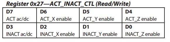
"Then THRESH_ACT register is eight bits and holds the threshold value for detecting activity. The data format is unsigned, so the magnitude of the activity event is compared with the value in the THRESH_ACT register. The scale factor is 62.5 mg/LSB."

THRESH_INACT register has a similar task which holds the threshold for the inactivity. After setting thresholds, I set the FREE_FALL register which can detect the free-fall.


ADXL345 has two interrupt pin but eight interrupt sources. Therefore, we need to map the interrupts for the pins. I am using activity, inactivity, free-fall interrupts (maybe data available when my design becomes more clear).

image

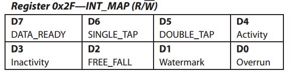
Any bits set to 0 in this register send their respective interrupts to the INT1 pin, whereas bits set to 1 send their respective interrupts to the INT2 pin. All selected interrupts for a given pin are OR’ed.

I will use interrupt pin 1 for the inactivity and free-fall and interrupt pin 2 for the activity (activity is used to double check). Therefore, I need to write 0bxxx100xx (0b11110011).


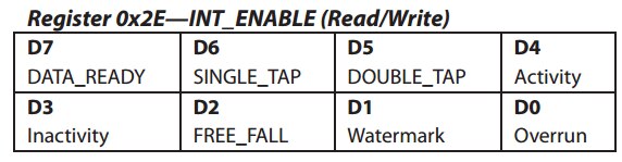
After setting all the values, we need to enable interrupts so we need to send 0b00011100 to INT_ENABLE register.

image


Here is the initialization code for the ADXL345. I coded this as a library file but I2C_transfer function can be only called from inside the task. Therefore following function is a task.


void ADXL345_init (UArg arg0, UArg arg1)
{
          uint8_t         txBuffer[2];
          uint8_t         rxBuffer[2];
          I2C_Handle      i2c;
          I2C_Params      i2cParams;
          I2C_Transaction i2cTransaction;


          /* Create I2C for usage */
          I2C_Params_init(&i2cParams);
          i2cParams.bitRate = I2C_100kHz;
          i2c = I2C_open(adxl345_I2C, &i2cParams);
          if (i2c == NULL) {
              System_abort("Error Initializing I2C\n");
          }
          else {
              System_printf("I2C Initialized!\n");
          }


          /**** ADXL345 TURN ON ***/


          txBuffer[0] = ADXL345_POWER_CTL;  //Wakeup
          txBuffer[1] = 0;
          i2cTransaction.slaveAddress = ADXL345_I2C_ADDR;
          i2cTransaction.writeBuf = txBuffer;
          i2cTransaction.writeCount = 2;
          i2cTransaction.readBuf = rxBuffer;
          i2cTransaction.readCount =1;


          I2C_transfer(i2c, &i2cTransaction);


          txBuffer[1] = 16;               // Auto_sleep
          I2C_transfer(i2c, &i2cTransaction);


          txBuffer[1] = 8;               // Measure
          I2C_transfer(i2c, &i2cTransaction);


          /***** Give the range settings *****/
          // Accepted values are 2g, 4g, 8g or 16g - ADXL345_DATA_FORMAT
          // Higher Values = Wider Measurement Range
          // Lower Values = Greater Sensitivity


          /**** Activity Inactivity setting  ***/


          txBuffer[0] = ADXL345_ACT_INACT_CTL;
          txBuffer[1] = 0b01110111;
          I2C_transfer(i2c, &i2cTransaction);


          txBuffer[0] = ADXL345_TIME_INACT; //
          txBuffer[1] = 10;
          I2C_transfer(i2c, &i2cTransaction);


          /**** Activity Threshold  ***/


          txBuffer[0] = ADXL345_THRESH_ACT;
          txBuffer[1] = 75; // 62.5mg per increment    // Activity thresholds (0-255)
          I2C_transfer(i2c, &i2cTransaction);


          /**** Inactivity Threshold  ***/


          txBuffer[0] = ADXL345_THRESH_INACT;
          txBuffer[1] = 20; // 62.5mg per increment    // Inactivity thresholds (0-255)
          I2C_transfer(i2c, &i2cTransaction);


          /**** Free-Fall Threshold and Time ***/


          txBuffer[0] = ADXL345_THRESH_FF;
          txBuffer[1] = 7;  // (5 - 9) recommended - 62.5mg per increment
          I2C_transfer(i2c, &i2cTransaction);


          txBuffer[0] = ADXL345_TIME_FF;
          txBuffer[1] = 30; // (20 - 70) recommended - 5ms per increment
          I2C_transfer(i2c, &i2cTransaction);


          /**** Interrupt setup  ***/


          //Interrupt mapping


          txBuffer[0] = ADXL345_INT_MAP;
          txBuffer[1] = 0; // 0b11110011;  //inactivity and free-fall is int1, activity is int2 ( others are int 2 but disabled)
          I2C_transfer(i2c, &i2cTransaction);


          //Interrupt enable


          txBuffer[0] = ADXL345_INT_ENABLE;
          txBuffer[1] = 0b00011100;  //activity, inactivity, and free-fall interrupts are enabled
          I2C_transfer(i2c, &i2cTransaction);


          /* Deinitialized I2C */
          I2C_close(i2c);
          System_printf("I2C closed!\n");
          System_flush();


          /* Construct BIOS objects */
          Task_Params taskParams;


          Task_Params_init(&taskParams);
          taskParams.stackSize = TASKSTACKSIZE;
          taskParams.stack = &taskI2CStack;
          Task_construct(&taskI2CStruct, (Task_FuncPtr)readPos, &taskParams, NULL);


}


ADXL345 has the interrupt output so we need to get this on MSP432. It was a little trick to find how interrupts work on TI-RTOS then it becomes very easy. First, MSP_EXP432P401R.c should be configured. I set up the p3.6 pin for the INT1 output of the ADXL345 so I added the following code to gpioConfigs driver. Then give that pin a name inside MSP_EXP432P401R.h.


    /* MSP_EXP432P401R_P3.6 */

    GPIOMSP432_P3_6 | GPIO_CFG_IN_PU | GPIO_CFG_IN_INT_FALLING,


MSP_EXP432P401R.c Pin Configuration

GPIO_PinConfig gpioPinConfigs[] = {
    /* Input pins */
    /* MSP_EXP432P401R_S1 */
    GPIOMSP432_P1_1 | GPIO_CFG_IN_PU | GPIO_CFG_IN_INT_RISING,
    /* MSP_EXP432P401R_S2 */
    GPIOMSP432_P1_4 | GPIO_CFG_IN_PU | GPIO_CFG_IN_INT_RISING,


    /* MSP_EXP432P401R_P3.6 */
    GPIOMSP432_P3_6 | GPIO_CFG_IN_PU | GPIO_CFG_IN_INT_FALLING,


    /* Output pins */
    /* MSP_EXP432P401R_LED1 */
    GPIOMSP432_P1_0 | GPIO_CFG_OUT_STD | GPIO_CFG_OUT_STR_HIGH | GPIO_CFG_OUT_LOW,
    /* MSP_EXP432P401R_LED_RED */
    GPIOMSP432_P2_0 | GPIO_CFG_OUT_STD | GPIO_CFG_OUT_STR_HIGH | GPIO_CFG_OUT_LOW,


    /*
     * MSP_EXP432P401R_LED_GREEN & MSP_EXP432P401R_LED_BLUE are used for
     * PWM examples.  Uncomment the following lines if you would like to control
     * the LEDs with the GPIO driver.
     */
    /* MSP_EXP432P401R_LED_GREEN */
    //GPIOMSP432_P2_1 | GPIO_CFG_OUT_STD | GPIO_CFG_OUT_STR_HIGH | GPIO_CFG_OUT_LOW,
    /* MSP_EXP432P401R_LED_BLUE */
    //GPIOMSP432_P2_2 | GPIO_CFG_OUT_STD | GPIO_CFG_OUT_STR_HIGH | GPIO_CFG_OUT_LOW
};


MSP_EXP432P401R.h Pin tagging


typedef enum MSP_EXP432P401R_GPIOName {
    MSP_EXP432P401R_S1 = 0,
    MSP_EXP432P401R_S2,
    MSP_EXP432P401R_INT1,
    MSP_EXP432P401R_LED1,
    MSP_EXP432P401R_LED_RED,


    /*
     * MSP_EXP432P401R_LED_GREEN & MSP_EXP432P401R_LED_BLUE are used for
     * PWM examples.  Uncomment the following lines if you would like to control
     * the LEDs with the GPIO driver.
     */
    //MSP_EXP432P401R_LED_GREEN,
    //MSP_EXP432P401R_LED_BLUE,


    MSP_EXP432P401R_GPIOCOUNT
} MSP_EXP432P401R_GPIOName;


Finally, activate the interrupt inside the main function.


    /* install Button callback */
    GPIO_setCallback(MSP_EXP432P401R_INT1 , gpioButtonFxn0);


    /* Enable interrupts */
    GPIO_enableInt(MSP_EXP432P401R_INT1 );


Now the design has the same features with the previous one but Arduino is removed. This make it more compact, cheaper, and more based on MSP432 image


You can see all the links related to this project in the first blog: Safe & Sound Wearables - Trackable Safety Helmet for Miners #1: Introduction to Project

  • Sign in to reply

Top Comments

  • DAB
    DAB over 8 years ago +1
    Nice update. It is encouraging to see stock software work as advertised. DAB
  • Jan Cumps
    Jan Cumps over 8 years ago in reply to msimon

    I have seen it in other people's code too. I don't know if there's a downside.

    • Cancel
    • Vote Up 0 Vote Down
    • Sign in to reply
    • More
    • Cancel
  • msimon
    msimon over 8 years ago in reply to Jan Cumps

    I need to use Semaphore hence there is no data between tasks. I just wonder are there any disadvantage of creating task inside a task?

    • Cancel
    • Vote Up 0 Vote Down
    • Sign in to reply
    • More
    • Cancel
  • Jan Cumps
    Jan Cumps over 8 years ago in reply to msimon

    By the way, there should be better way of creating task after a task but this is my first RTOS code. I don't know how to use rtos effectively yet.


    You can make a task wait until it receives a signal from another task. While waiting, it doesn't use processor time. It's parked.

    You can use Semaphores (if you just need to signal the second task it has to run and no data between the tasks) or Mailbox (if you want to send data from one task to the second one).


    • Cancel
    • Vote Up 0 Vote Down
    • Sign in to reply
    • More
    • Cancel
  • msimon
    msimon over 8 years ago in reply to jomoenginer

    Hi jomoenginer,


    You are right, it is confusing. Because I make the system work but not decided how the system will act based on the data and the names are not clear. Yes, I defined a task inside a task. ADXL345_init task is required to run once and then it created a task called readPos. readPos read the values from I2C bus (temperature and gyro) every second. I will change this function it just shows the system working. It may be called 50 times per second.


    I didn't use the button0 callback function it is my laziness to change the function name. Pin 3.6 is used for ADXL345 interrupt.


        GPIOMSP432_P3_6 | GPIO_CFG_IN_PU | GPIO_CFG_IN_INT_FALLING, 


    The code above is the configuration of the pin and MSP_EXP432P401R_INT1 is the tag for that pin so GPIO_setCallback(MSP_EXP432P401R_INT1 , gpioButtonFxn0);  assign pin 3.6 interrupt to gpioButtonFxn(it can be any name). It is dummy function and currently toggling an LED but it will send an emergency message to the main centre at the end.


    Finally, BIOS scheduler is called in the main function but it is not here. I am always adding the code inside the WiFi module RTOS code provided by TI so this article is a patch for that. You are right it is very confusing but it will be clear if I change the name and publish the full code. I will consider this in the next article.


    By the way, there should be better way of creating task after a task but this is my first RTOS code. I don't know how to use rtos effectively yet.


    Thanks,

    Mehmet

    • Cancel
    • Vote Up 0 Vote Down
    • Sign in to reply
    • More
    • Cancel
  • jomoenginer
    jomoenginer over 8 years ago

    I'm a bit confused with the code you posted.  You state your ADXL345_init function is a task yet you define a task inside the init function but with the task function being defined as 'readPos'.  Then in your main where you show where you activate the Interrupt, you show the button0 callback function being initialized.  At what point do you define and initialize the Interrupt for the ADXL345 as well as start the BIOS scheduler?  I posted something recently on how to set-up hardware Interrupts using the TI-RTOS example "gpiointerrupt_MSP_EXP432P401R_TI".  This might be a good reference for you.

    • Cancel
    • Vote Up 0 Vote Down
    • Sign in to reply
    • More
    • Cancel
>
element14 Community

element14 is the first online community specifically for engineers. Connect with your peers and get expert answers to your questions.

  • Members
  • Learn
  • Technologies
  • Challenges & Projects
  • Products
  • Store
  • About Us
  • Feedback & Support
  • FAQs
  • Terms of Use
  • Privacy Policy
  • Legal and Copyright Notices
  • Sitemap
  • Cookies

An Avnet Company © 2025 Premier Farnell Limited. All Rights Reserved.

Premier Farnell Ltd, registered in England and Wales (no 00876412), registered office: Farnell House, Forge Lane, Leeds LS12 2NE.

ICP 备案号 10220084.

Follow element14

  • X
  • Facebook
  • linkedin
  • YouTube