Connectors
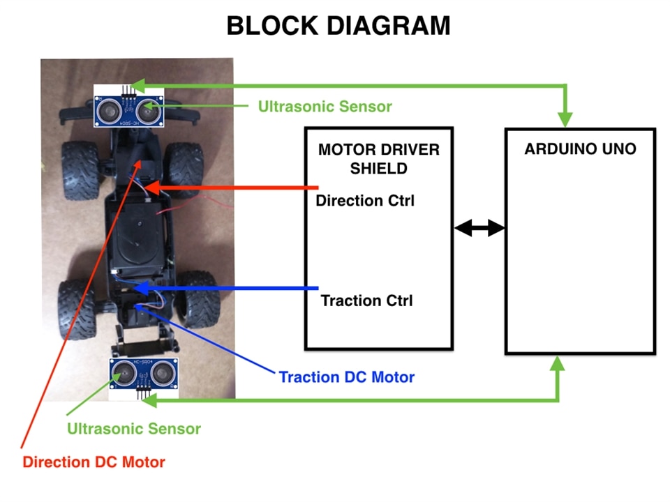
Going back to the block diagram, I will add a few comments here.

As a general principle, I would like to be able to disconnect the two engines, two sensors and two power supplies (not pictured in the diagram: 5V power bank and 6V engine power supply) from the Arduino stack in case I want to restore the truck to its original condition.
The solution I have in mind is to design an ArduMobo shield that will go on top of the motor driver shield. The shield will have 3 connectors (4 position screw-in type as the one used on the DF-robot DRI0017 board). Two connectors will be used to connect the sensors (4 wires each: VCC, GND, TRIG, ECHO), the other connector will handle power wires for the two power supplies (VCC1, GND1, VCC2, GND2). The board will have power switches and LED indicators for both power supplies.
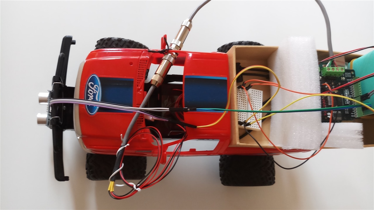
In order to connect the two engines (traction and steering) to the driver shield I used the T4011019041-000 pair of connectors (male female). Using this connector was pretty straightforward: no soldering, no crimping is needed, one needs to simply use the small Allen key (provided with the connectors) to screw the stripped wires in place (M4473 SL005 2 pair shielded cable from the kit). These metal connectors feel very solid: the cable is held in place tightly by pressure applied to the cable by a plastic and rubber circular assembly inside the metal enclosure. This connector is indeed very solid, well designed and manufactured.

Crimping adventures
To connect the two sensors I selected two D-1000 4 position connectors.
To connect the power supply I selected the circular plastic connectors (206153-1 female and 206060-1 male).
Until now I mostly used Dupont jumping wires and I did not assemble any connectors so I had no crimping tools. For reasons I will not waste your time explaining, I have quite a few mini connectors which I identified to be of JST type.
Without spending much time reading about crimping, I read a few reviews online and I ordered an IWISS crimping tool (SN-2549) thinking that I will be able to use it to crimp both the JST connectors I already have and also the D-1000 and the circular plastic ones.
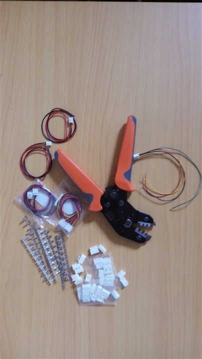
The IWISS SN-2549 crimping tool worked very nicely on the JST connectors (set on the second crimping slot from the tip of the die). Next picture shows the crimping tool and the JST style connectors, with the harness I crimped on the right of the image).

This crimping tool can also be used for the D-1000 plated contacts. It is a rather cumbersome process: the contact has to be placed into the first slot of the die, the most narrow slot that is. Placing the contact on any other crimping slot will damage the contact (the thickness of the die is too big, and you will end up flattening the little metal blade that acts as a tiny spring and secures the contact into the receptacle).
Much to my chagrin, the SN-2549 crimping tool does not work for the closed contacts of the circular plastic connector, the thickness of the die being simply too large.
At this point I decided to read a bit more about crimping (open barrel & closed barrel contacts, die profiles, die width and thickness, crimping tools, ratcheting mechanisms and crimping force adjustment, tool cost, AWG spec, etc…). I also read a few crimping tools reviews and came to the conclusion that an IWISS 2028M crimper will work for both D-1000 and the 206153-01/206060-02 connectors. Last week I ordered this tool and I will update the blog once I receive it.
https://www.amazon.com/IWISS-Crimping-AWG28-20-Terminals-Connectors/dp/B078WNZ9FW
In the end, many thanks to TE Connectivity for providing such a nice kit for the challenge. I was not familiar with the company but now I really appreciate the quality of their connectors and plan to use their D-1000 series for all my future connectors (especially the ones that need frequent plugging in and out). Also many thanks to the organizers with a special thank you note that goes to Randall who promptly shipped some extra needed pins and sockets.
For some reason my camera just died and I am unable to post good quality close-up photos of connectors because my phone does not take acceptable quality images at close range. I will update the blog with close-up photos once I get a new camera.
Best wishes to all fellow competitors.
