


Let's meet the arm (or rather arm joint) of the robot that doesn't exist as of yet!
Mechanical assembly of robot arm
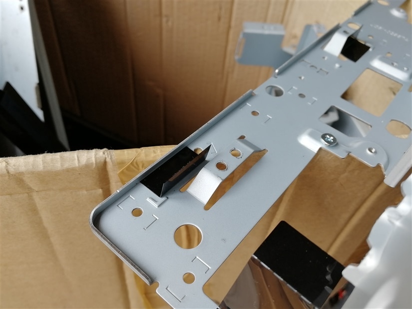
I had some printer parts (motors, gears, sheet metal parts) that I wanted to use to create this robot. Also, I had thought of using the scanner (moving bit) to use as an arm/leg but that didn't work out very well. This is because after experimenting, I found that the power supplied to the motor wasn't enough to generate enough torque to overcome the inertia of the whole part.


So, I had to use slightly bigger motor and make the arm from other parts. I found a DC motor, metal brackets, and plastic gears. I had bought some encoders and potentiometers to use as angular sensors in this project so that came in handy when I wanted to build this arm.
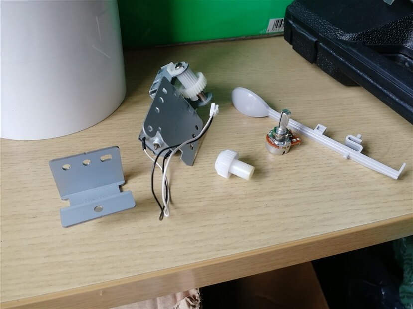
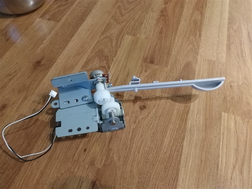
So anyways, after spending a few hours, I made an assembly that looks like shown in the pictures below. The spoon kind of thing in the pitcure is meant to be an arm which is also sourced from one of the dismantled printers! 

Now, let's talk about the code.
Code for controlling the arm
I used Arduino Uno as the main control computer for the robot arm and used the shield DFR0502 provided in the kit. Details for the shield are here: https://wiki.dfrobot.com/Gravity_IO_Expansion_%26_Motor_Driver_Shield_V1.1_SKU__DFR0502
There was some inconsistency regarding the motor function which I had to debug and now corrected in my code below. The wiring is quite straight forward as shown in their link and additionally, I hooked up the potentiometer to A0 on Arduino Uno.
I had tried to use PID controller for this arm. However, after much debugging on why it didn't perform as it should, I found that the motor didn't respond very well with PWM output of lower than 220 (out of scale 0 - 255 on Arduino Uno). This made it difficult for me to implement variable power input into the motor as per the error given by the difference between the setpoint (set angle) and actual point (angle). So finally, I ended up using just a bang bang control structure with a band where the motor was kept idle. I used band of inactivity to avoid motor hunting around the setpoint when it doesn't quite reach there and overshoots above and below it with the given power to the motor. Anyways, here is the code which I will explain below.
/*
* Project: element14 community - twist, turn and move design challenge
  Author: Hitesh Boghani
*/

#define POT1 0

int potVolts;
int error;
int setPoint = 800;

void motor_c(char motor_n, char direction_m, int speed_m) /* motor_n: the motor number to drive(0 stands for M1;1 stands for M2)*/
/* direction_m : the motor rotary direction(0 is clockwise and 1 is counter-clockwise).*/
/* speed_m: to control the motor rotation speed(from 0 to 255 ), the speed_m value is larger, the rotation speed is faster;*/
{
  if (motor_n == 0) {
    if (direction_m == 1) {
      digitalWrite(4, HIGH);    // pin 4 controls M1 rotary direction
      analogWrite(5, speed_m);  //pin 5 controls M1 rotation speed
    } else {
      digitalWrite(4, LOW);
      analogWrite(5, speed_m);
    }
  } else {
    if (direction_m == 1) {
      digitalWrite(7, HIGH);    // pin 7 controls M2 rotary direction
      analogWrite(6, speed_m);  //pin 6 controls M2 rotation speed
    } else {
      digitalWrite(7, LOW);
      analogWrite(6, speed_m);
    }
  }
}

void setup() {
  Serial.begin(9600);
}

void loop() {
  if (Serial.available()) {
    setPoint = Serial.parseInt();
    Serial.println(setPoint);
  }

  potVolts = analogRead(POT1);
  error = setPoint - potVolts;
  Serial.print("Error is: "); Serial.println(error);

  if (error < -10) {
    motor_c(0, 0, 255); // go backwards
    Serial.println(". So, going backwards");
  }
  if (error > 10) {
    motor_c(0, 1, 255); // go forwards
    Serial.println(". So, going forwards");
  }
  if (error <= 10 && error >= -10) {
    motor_c(0, 1, 0);
  }

  delay(1);

}
After the usual definitions and declarations, I have copied DFRobot's function to control the motor. It makes things easier because it handles the direction, speed and output pins. You will notice that I have changed line 16 from
This basically made sure that motor 1 outputs were getting activated correctly as per the board markings as opposed to motor 2.
In line 40 - 43, the program is looking at the input given via serial comms and parsing integer from it to use as setpoint. There should be caution provided here that if you are using Arduino IDE's serial monitor then 'No Line Ending' should be selected. This is because, in my experience, I found that the integer parser was getting 0 because of line ending and it was setting the setpoint to 0 in the next sampling period. So, choosing the 'No Line Ending' option will avoid this issue.
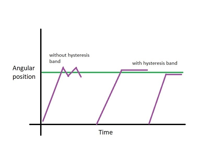
Line 49 - 59 is effectively the bang bang type controller where if the error is negative, full effort (PWM 255, in direction 0) is applied to drive the error down to zero. If the error is positive, full effort (PWM 255, in direction 1) is applied. So, one can imagine that because of motor+gear+arm inertia, delays in the system and full power, the position will overshoot the desired postion and suddenly the program will apply the opposite direction full force, and so on. This is not desirable. This is why I have put a band in line 57 - 59 where the motor does nothing. This is illustrated with a doodle below where without the hysteresis band, the motor starts hunting around the setpoint and with the band, does not.
Of course, it won't be accurate because the motor will stop either too late or too early. Ideally, if precise positioning is desired, PID or other advanced control algorithms should be used. In this scenario though, I didn't have a problem using this controller because it didn't matter if the arm was a couple of degrees off the desired position as this was only intended to show position of the arm in Yoga posture. Please note that I had total increments of 750 from the analogRead for 180 degrees.
OK so now that is enough explanation of the code and reasoning, let's get to action! Here is the video of this arm where I am positioning the arm in several different positions using keyboard entry into the serial monitor.
This is for the demonstration purposes only and in future, this will be coordinated movement with other parts of the robot. Additionally, I should mention here that I am going to implement the code in freeRTOS for arduino so that simultaneous movements of the robot joints can be realised.
Stay tuned for more robot limbs and joints! ;)


