Just like at work, as a proposal develops into the prototype, the spec changes on the lessons learned during the build.
My best wish would to have several of these SMD relays in the final design. For expediency, I'm using just the one provided in the TE kit.
https://www.te.com/usa-en/products/brands/axicom/axicom-im-relays.html?tab=pgp-story
I changed where this relay can be best leveraged in the Pool Butler at least 3 times, so to ensure flexibility,
I've committed what could be considered a technical foul (?) .
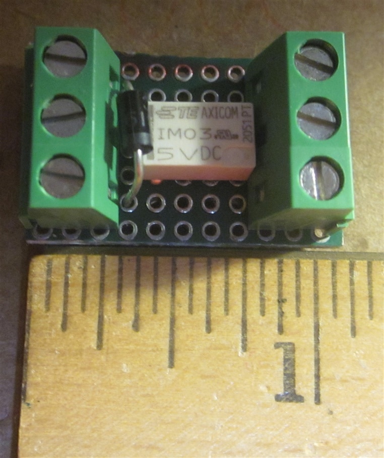
**** The SMD relay was mounted on a thru hole board. *******
No SMD protoboards in my makerspace inventory, maybe something to consider adding in the future.
Would protoboards like these work for this relay ?
What did I do to make it work ?
Using a small pair of needle nose pliers, the SMD legs were bent down like a thru hole design. The legs are thin, so care must be taken.
After the pin straightening was done, the legs were bent ever so slightly to the left or right as needed to fit in the thru holes.
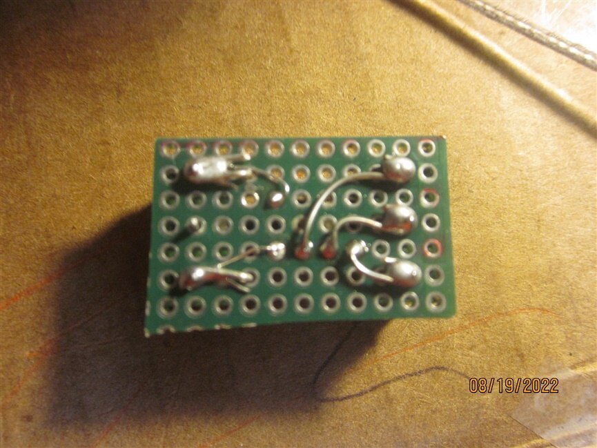
22 AWG was used to wire from the C form contacts to the terminal board stabs. The wires were bend to go into the thru holes and make contact with the SMD legs, then solder flowed to fill the thru hole. Only one set of contacts were wired to TBs.
28 or 30 AWG was used for the 20 mA required for the 5V relay coil. I also used a tremendously oversized flyback diode on the relay coil.
It was a little effort, but this way the diode is installed on the relay card, and the size is just as small as would be with a SMD protoboard.
This relay card can be reused later in other projects if it survives the Pool Butler.


I usually use a hot glue gun for fastening little device boards in a prototype.
The hot glue is non conductive and with a little heat can be convinced peel off. It cant be used in projects that sit in the sun or get pretty warm.
