


This is blog #8 - Everything you did and didnt want to know about the mystical and magical Pool Butler Steering system
1. The video of the steering operation in drydock. https://youtu.be/54yKQ6vUuSc
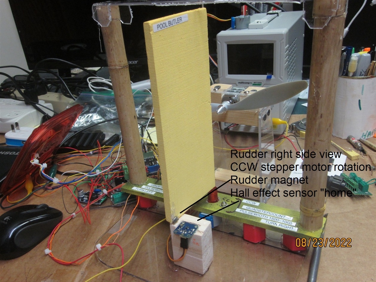
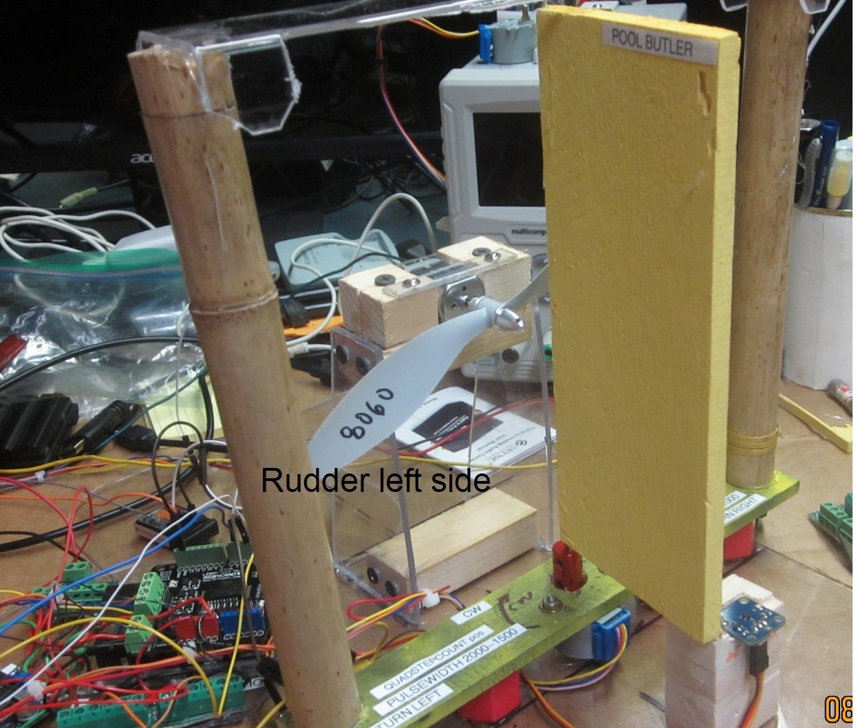
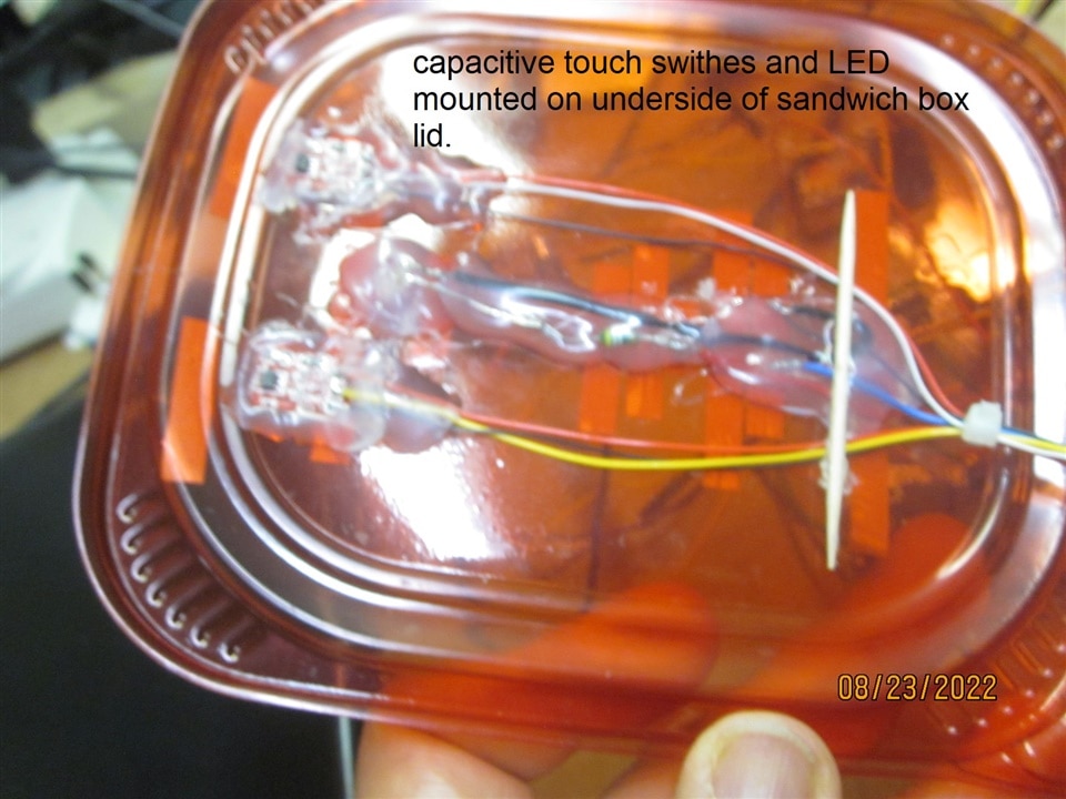
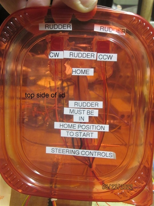
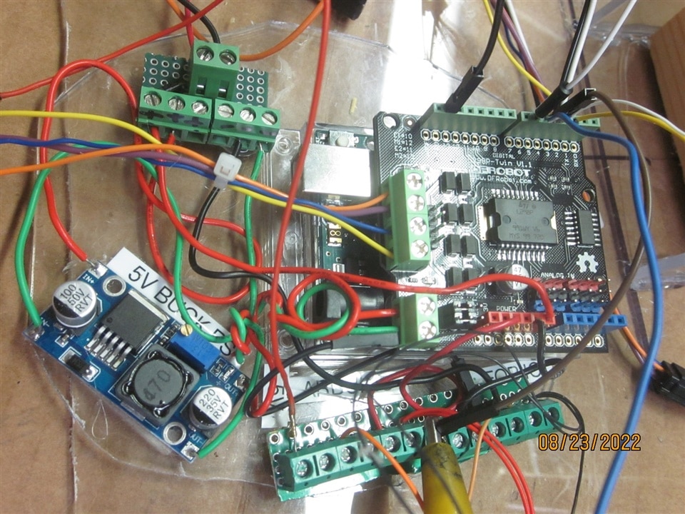
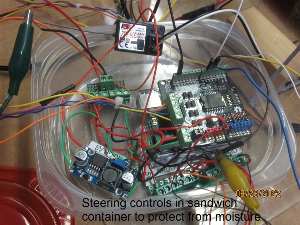
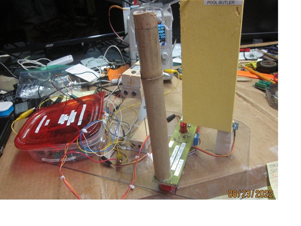
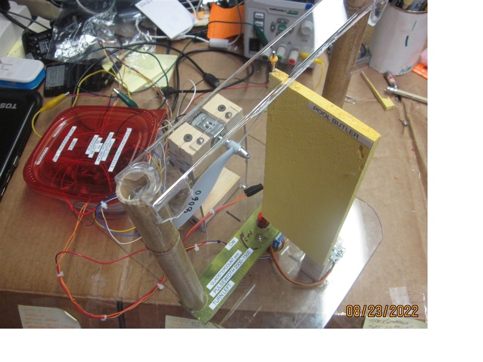
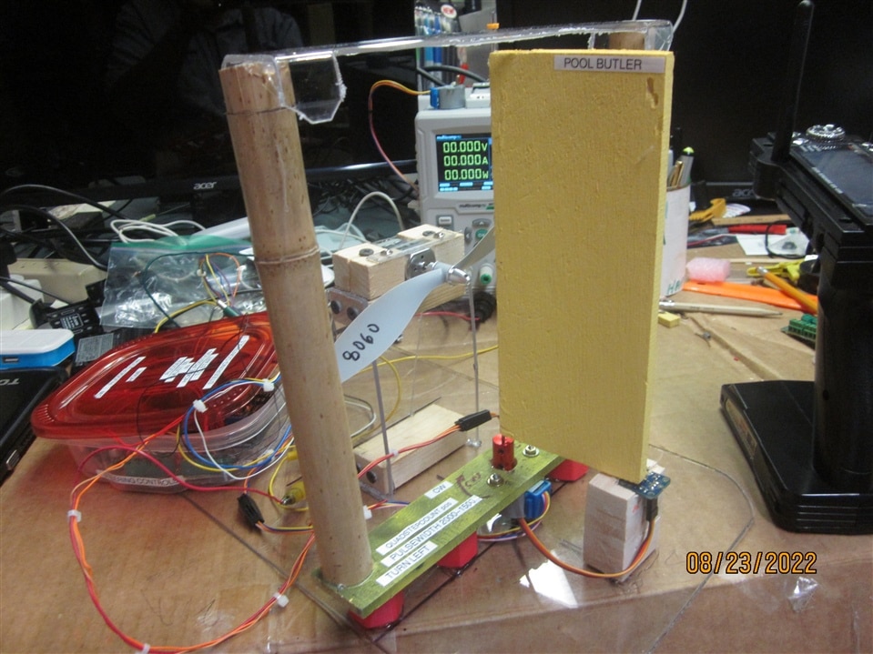
2. some photos
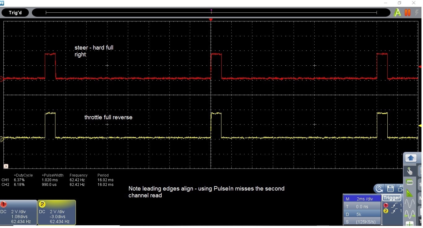
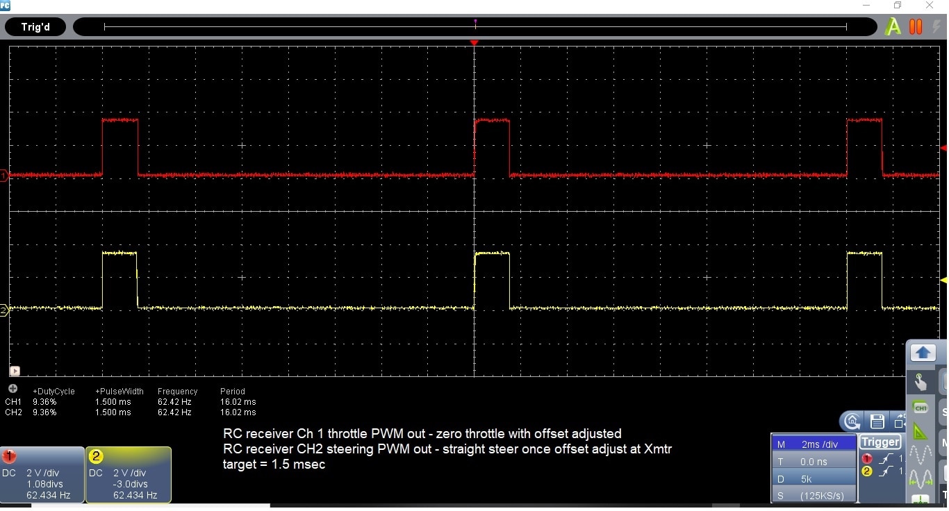
3. screen shots of the scope timing of the FS_GR3E radio receiver PWM output timing
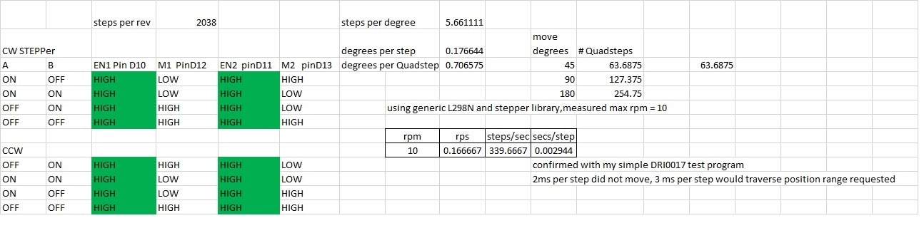
4. engineering calculations for the stepper motor
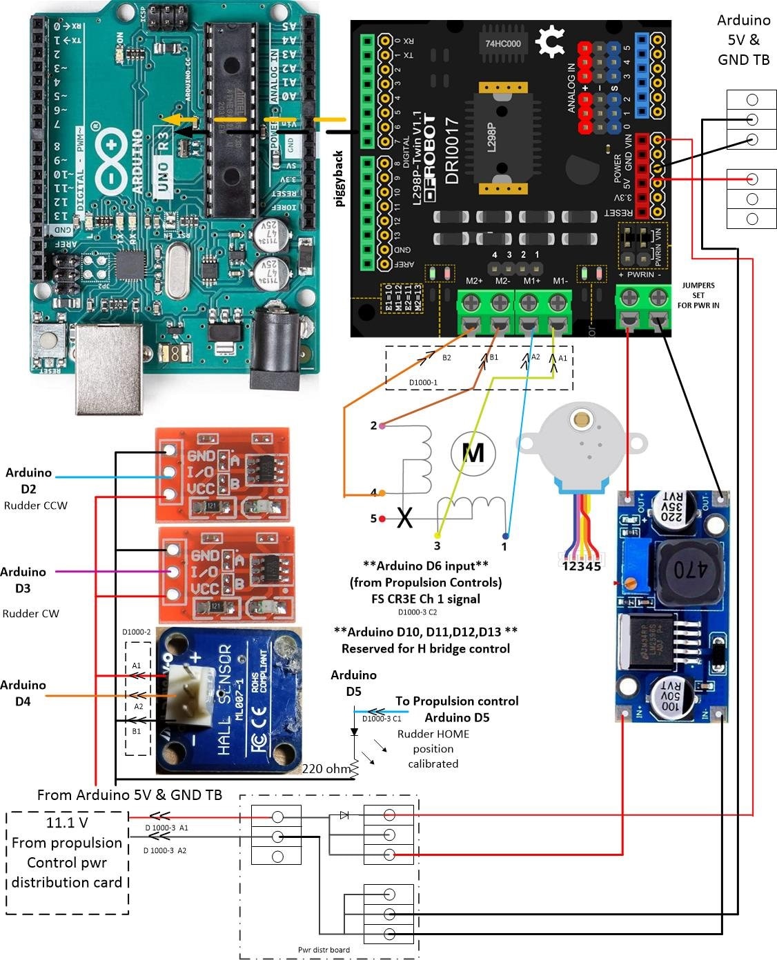
5. The steering control system schematic with TE connectors shown
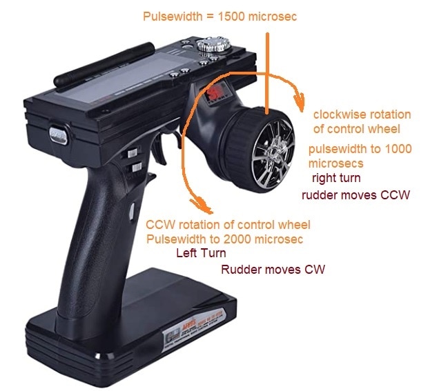
6. Steering system devices , directions and scalings.
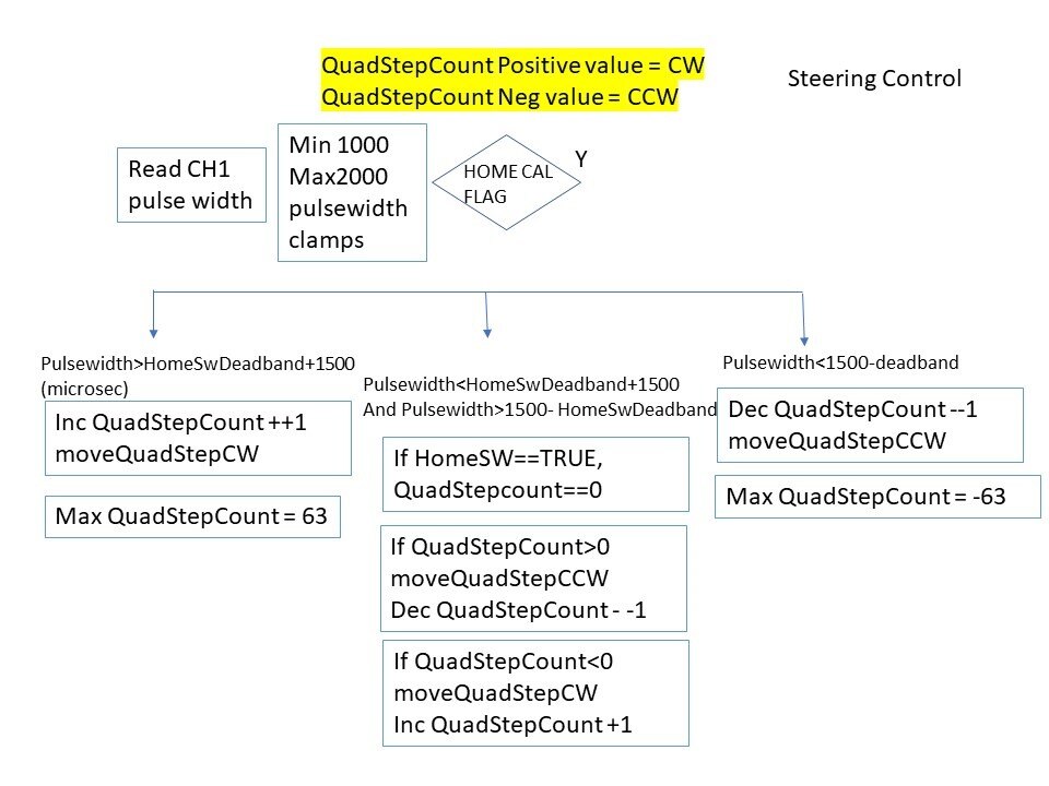
7. Steering system software flowchart
8. The Steering system Arduino code with debugging code commented out
1. The video of the steering operation in drydock. https://youtu.be/54yKQ6vUuSc
2. some photos
3. The screen shots show why separate Arduinos were used for propulsion and steering. 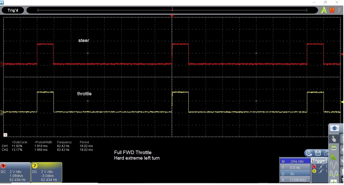
4. stepper engineering calcs
5. steering control system schematic
6. steering system device conventions
7. software flowchart
8. finally, the steering controls Arduino code:
// ---------------------------------------------------------------------------
// StepperTest_DRI0017_SteeringWorksOpenLoop.ino
//
//StepperTest_DRI0017.ino is the starting point. It is a simple test of the stepper motor rotation.
// Ver2 adding the Move Rudder CCW and Move Rudder CW PBs and the home switch
// This version adds the RC input. If the steering moves past the PAR.SteeringDeadband,then the QuadStepRef gets incremented or decremented.
//
// *** MEASURED DATA ****
// channel 1 is used for turning, speed ratio
// CH1_PWMtime center = 1509 to 1516 usec pulsewidth
// CH1_PWMtime full left = 1073 usec pulsewidth, joystick left side slows down LHS motor
// CH1_PWMtime full right = 1922 usec pulsewidth, joystick right side slows down RHS motor
// ---------------------------------------------------------------------------
int stepWidth=4; // 3 msec is the lowest value that can be used with the 12BYJ-48 stepper motor
int E1=LOW; // E1 is physically connected to Arduino D10
int E2=LOW; // E2 is physically connected to Arduino D11
// M1 is physically connected to Arduino D12
// M2 is physically connected to Arduino D13
int RudderHomeSW=LOW;
int MoveRudderCW_PB=LOW;
int MoveRudderCCW_PB=LOW;
int RudderHomeCalibrated=LOW;
int RCTransmitterOff=LOW; // VAR if CH1 pulsetime = 0 means transmitter is off
int SteeringDeadband=100; // number of msec counts + or - of 1500 to signify the steering wheel is really turned
int QuadStepCount=0; // the count of quad steps while the stepper moves, a psuedo position fbk
unsigned long CH1_PWMtime; //pulsewidth time of Channel 1 (into pin 2) RC in microseconds, 1000 = full REV (or -90 degress), 1500=zerospeed or 0 degrees, 2000=full FWD (or +90 degrees)
unsigned long timeout = 23000; //timeout of PWM , set timeout for reading a pulsewidth at 15% moree than max expected 20ms (tried 2300 and caused problems)
int CH1_PWMtime_int; // CH1_PWMtime is an unsigned long, convert it to integer as value will not overflow int
void setup() {
pinMode(2, INPUT); // manually move rudder CW - left drive side
pinMode(3, INPUT); // manually move rudder CCW - right passenger side
pinMode(4, INPUT); // rudder at home position , zero degree position thyis is a start permissive for the airboat
pinMode(6, INPUT); // RC receiver Channel 1 LHS side motor control
pinMode(5, OUTPUT); // Rudder Home switch Calibrated
pinMode(10, OUTPUT); // E1 is physically connected to Arduino D10
pinMode(11, OUTPUT); // E2 is physically connected to Arduino D11
pinMode(12, OUTPUT); // PWM RHS motor (passenger side) in FWD, low in reverse (test with LED)
pinMode(13, OUTPUT); // PWM RHS motor (passenger side), low in FWD (test with LED)
// Serial.begin(115200);
}
void QuadStepCCW()
{
E1=HIGH;
digitalWrite(10,E1);
E2=HIGH;
digitalWrite(11,E2);
//STEP 1
digitalWrite(12,LOW); //M1 positive
digitalWrite(13,HIGH); //M2 negative
delay (stepWidth); // step speed in msec
//STEP 2
digitalWrite(12,LOW); //M1 positive
digitalWrite(13,LOW); //M2 positive
delay (stepWidth); // step speed in msec
//STEP 3
digitalWrite(12,HIGH); //M1 neg
digitalWrite(13,LOW); //M2 positive
delay (stepWidth); // step speed in msec
//STEP 4
digitalWrite(12,HIGH); //M1 neg
digitalWrite(13,HIGH); //M2 neg
delay (stepWidth); // step speed in msec
}
void QuadStepCW()
{
E1=HIGH;
digitalWrite(10,E1);
E2=HIGH;
digitalWrite(11,E2);
//STEP 1
digitalWrite(12,HIGH); //M1 positive
digitalWrite(13,LOW); //M2 negative
delay (stepWidth); // step speed in msec
//STEP 2
digitalWrite(12,LOW); //M1 positive
digitalWrite(13,LOW); //M2 positive
delay (stepWidth); // step speed in msec
//STEP 3
digitalWrite(12,LOW); //M1 neg
digitalWrite(13,HIGH); //M2 positive
delay (stepWidth); // step speed in msec
//STEP 4
digitalWrite(12,HIGH); //M1 neg
digitalWrite(13,HIGH); //M2 neg
delay (stepWidth); // step speed in msec
}
void loop()
{
// This is the manual adjustment portion of the rudder home position
// Calibration is only done once, then the calibration flag is sealed in
MoveRudderCW_PB=digitalRead(3);
MoveRudderCCW_PB=digitalRead(2);
RudderHomeSW=digitalRead(4);
if ((MoveRudderCW_PB==HIGH)&& (RudderHomeSW==LOW)&&(RudderHomeCalibrated==LOW))
{QuadStepCW();}
if ((MoveRudderCCW_PB==HIGH)&& (RudderHomeSW==LOW)&&(RudderHomeCalibrated==LOW))
{QuadStepCCW();}
// **** rudder calibration ****
if ((RudderHomeSW==HIGH)&&(RudderHomeCalibrated==LOW))
{ RudderHomeCalibrated=HIGH;}
digitalWrite(5,RudderHomeCalibrated);
// Serial.print("RudderHomeSW =");
// Serial.println(RudderHomeSW);
// Serial.print("RudderHomeCal =");
// Serial.println(RudderHomeCalibrated);
// Reads a pulse (either HIGH or LOW) on a pin. For example, if value is HIGH, pulseIn() waits for the pin to go HIGH, starts timing, then waits for the pin to go LOW and stops timing. Returns the length of the pulse in microseconds. Gives up and returns 0 if no pulse starts within a specified time out.
// Works on pulses from 10 microseconds to 3 minutes in length.
CH1_PWMtime = pulseIn(6, HIGH, timeout); // pulseIn(pin, value, timeout) value is HIGH or LOW, timeout and value are long int
//if the transmitter is OFF Pulsetime=0
//Serial.print("CH1 Time: ");
//Serial.println(CH1_PWMtime);
// The cast operator translates one variable type into another and forces calculations to be performed in the cast type.
// Syntax (type)variable Parameters: type: any variable type (e.g. int, float, byte)
CH1_PWMtime_int = (int) CH1_PWMtime; //convert unsigned long to int
//Serial.print("CH1 Time: ");
// Serial.println(CH1_PWMtime_int);
if (CH1_PWMtime_int==0) /// check to see if transmitter is turned off
{ RCTransmitterOff=HIGH;}
else
{ RCTransmitterOff=LOW;}
if ((RCTransmitterOff==LOW)&&(RudderHomeCalibrated==HIGH))
{
if (RudderHomeSW==HIGH)
{QuadStepCount=0;}
// RC wheel full CCW, Pulsewidth 1500-2000. want left turn. Rudder move CW. QuadStep count 0 to 63
// RC wheel full CW Pulsewidth 1000-1500. want right turn. Rudder move CCW . QuadStepCount 0 to -63
if ((((CH1_PWMtime_int)- (1500))>= SteeringDeadband )&& (QuadStepCount<63))
{
QuadStepCW();
QuadStepCount=QuadStepCount+1;
// Serial.println("Rotating CW");
// Serial.println(CH1_PWMtime);
// Serial.print("QuadStepCount= ");
// Serial.println(QuadStepCount);
delay(1);
}
// if the steering wheel returned to center, drive the stepper to home position
if ((CH1_PWMtime_int<(1500+SteeringDeadband))&& (CH1_PWMtime_int>(1500-SteeringDeadband)))
{
if (QuadStepCount<0) // when rudder is on CCW side , drive CW to center
{QuadStepCW();
QuadStepCount=QuadStepCount+1;
delay(1);
}
if (QuadStepCount>0) // when rudder is on CCW side , drive CW to center
{QuadStepCCW();
QuadStepCount=QuadStepCount-1; }
// Serial.println(CH1_PWMtime);
// Serial.print("go to home QuadStepCount= ");
// Serial.println(QuadStepCount);
delay(1);
}
if ((((1500)-(CH1_PWMtime_int))>= SteeringDeadband )&& (QuadStepCount>-63))
{ QuadStepCCW();
QuadStepCount=QuadStepCount-1;
// Serial.println("Rotating CCW");
// Serial.println(CH1_PWMtime);
// Serial.print("go NEG QuadStepCount= ");
// Serial.println(QuadStepCount);
delay(1);
}
//Serial.print("QuadStepCount= ");
//Serial.println(QuadStepCount);
// delay(100);
}
}


