


G'day Everyone,
I am looking forward to "The Ultimate RoadTest" and it'll be fun to report on my progress with TI's products and with some schematic diagrams and PCBs drawn using EAGLE.
I've selected "code name" as my project's name to be silly.
Something smells a bit Wiffy(WiFi)!
I can't wait to create and control my own WiFi peripherals from TI's microcontrollers and CC3000 through LS Research TiWi SL or muRata Modules.
WiFi through SPI for the masses with all the hard stuff already done and dusted.
For those of you with very small hands, just connect up 5 wires and power to the module and voila! Instant Internet accessible.
My hands aren't that small and it's even easier with TI's CC3000 FRAM SimpleLink Evaluation Kit where you just plug in the WiFi Module board and install the demonstration application.
FRAMBO - First Blood!
To FRAM or Flash - that is the question!
FRAM is non volatile memory technology with high performance and is capable of fast single bit updates!
I've previously used FRAM to build an CP/M 80 compatible system with USB peripheral and Disk drive support.
All it required was a single microcontroller and some FRAM.
(For those who are interested just send me a message for more information.)
Would you like Salt, Pepper or any other seasoning?
If I'm amibitious and have enough time, I may use solar power or other energy harvesting technologies for power to enable my peripherals to be truly independent and wireless!
Like the good old Aesop's tale about the Tortoise and the Hare two approaches can be used;
Slow and Steady
or
Fast with naps (provided the naps are not too long!)
(If only the Hare did not nap for too long!)
To have a monitoring system all year around that relies solely harvested power, seasonal climate changes need to be considered.
At the most extreme for Solar power, Winter at the North and South poles has really long nights.
So much for this banter.
The proof is in the pudding!
Cheers!
30th March
(!#$%- stupid web session timed out and lost all my new edits - Here's attempt number two.).
The First pudding - "It's just like packet cake mix but only electronic"
For this challenge the end application must be for the Home Automation market and must comprise of the following elements;
- Wireless
- Sensing
- Motor Control
- Lighting Technologies
Texas Instruments have invested a huge effort into the development and marketing of the CC3000, other SimpleLink products, MSP430s and MSP430FRAMs.
So much so that their demonstration and samples are quite impressive.
The included demonstration demonstrates the Wireless element using WiFI and sensing via a thermistor, Input Voltage and accelerometer.
To meet the qualifying criteria, the first (but not final pudding) be made from TI's Instant packet cake mixes with just a few extra condiments thrown in add the Motor Control and Lighting Technology elements.
Pardon the lack of marketing schpeel but the first application will be a very basic remote Home monitoring system.
(I don't want to be caught out like a well known phone and tablet manufacturer that boasted 4G functionality in their product when you're in a country that can't make use of it.)
From a remote device such as an WiFi Tablet or mobile phone;
- Receive the status of several sensors
- Control a HVAC Damper or fan.
- Control a simple dimmable light
Once this has been accomplished the pudding can be refined and additional functionality added.
I hope you enjoy this journey.
31st March
"A stitch in time saves nine"
Whilst eagerly waiting for the delivery of the CC3000, I have been taking this opportunity to read the associated literature and to watch the demonstration videos.
It's also a good opportunity to start familiarising myself with the tools such as Code Composer and EAGLE.
I've never used EAGLE before except for viewing an existing design.
I downloaded the latest version V6.1 and currently running in freeware mode until I have become more familiar with it.
I have started laying out my first PCB.
I've defined the board outline to the max 3.9in x 3.2in. - To me this was an unusual procedure. I've never used wires to define a board outline.
Then placed the RHA footprint for the MSP430FR573x microcontroller.
I was very happy to find tht the RHA footprint was in the Texas library because it saves me the time and effort of having to create my own library component.
Now, how do I....?
I just started my first schematic.
Poop! I spoke to soon. There's no MSP430FR573x/2x component in it. I will have to create my own library component or source it from elsewhere.
April Fool's Day
"LaunchPad preparations"
I opened up my MSP430 LaunchPad hoping that I can use it for preparing for the arrival of the CC3000 and MSP430FRAM kit.
I took this opportunity to use the CCS (Code Composer Studio v5) and MSP430ware for the first time.
To ensure that the process worked properly I used the blank MSP430G2211 that came with the LaunchPad.
I must say that it was very easy to use. The "Hello World" application for microcontrollers (i.e. Blinking a LED) was up and going within minutes.
All I did use the Resource manager, look through the MSP430ware folder and select the Blink LED example.
I did a build, invoked the debugger which loaded the microcode and pressed F8 to get it going.
I also used the debugger to single step through the code.
After that I manually created my own project to blink a LED to find that it was just as simple to accomplish.
I don't know whether it is applicable but no initialisation was required on my behalf except of the disabling of the Watchdog timer since I wasn't using it.
The summary of the preparations are:
#include <[Insert appropriate chip_header.h]>
main() {
[Insert Disable WDT statement]
[Insert app]
}
The MSP430G2211 has 10 I/O pins, an 8 channel comparator, a timer and watchdog timer (which also can be used as a normal timer)
The LaunchPad kit also comes with an MSP430G2231IN14.MSP430G2231IN14.. It's a bigger sister with an ADC, temperature sensor and USI Serial port but with no 8 channel comparator.
With the aid of the code examples the following elements have been attempted;
proto element 1
Output Control - The ability to control an output port bit. COMPLETE
proto element 2
Input Control - Read the status of an input port pin. COMPLETE
proto element 3
Lighting technologies - The onboard LED will be now dimmed under control. COMPLETE
PWM was used to accomplish this task.
proto element 4
Motor control - A servo motor is positioned under control. COMPLETE
Like proto element 3, PWM will used to accomplish this task.
I may get Wallace and Grommit to help out.
proto element 5
Real Time Reactivity - The ability to instantly react to a change of Input pin state. COMPLETE
My PWM Control Choice
There are a variety of methods of accomplishing PWM using an MSP430 but for the lowest power consumption, least CPU overhead and least code.
I just used the Timer and directed one of its outputs to an output pin.
It works every effectively. The heart is as follows;
P1DIR |= 0x04; // Set P1.2 as output
P1SEL |= 0x04; // Set P1.2 to use its peripheral option (TA0.1)
CCR0 = 511; // Set the PWM period
CCTL1 = OUTMOD_7; // Set to use the Set/Reset configuration
CCR1 = 64; // Set the Active portion of duty cycle
TACTL = TASSEL_2 + MC_1; //Configure the Timer ot use the SMCLK and Up mode
And optionally to put the CPU asleep
_BIS_SR(LPM0_bits);
To change the active portion of duty cycle just reprogram the CCR1 register with the desired value.
To confirm at its working I observed the output waveform on my MSO and also I hooked up an LED and 390 ohm resistor between P1.2 and GND and observed its behaviour to the signal.
A Handy Note: If you've put the CPU asleep, you'll need to wake it up to make any PWM duty cycle changes.
"The EAGLE has landed."
(I still can't get my head around WIRE = LINE. Why would I draw broken wires on a schematic? Lines yes. But wires?)
To create my new MSP430FR573x component I've given myself a crash course with the library editor.
I've discovered that a component comprises of three separate parts;
- Device
- Package (PCB)
- Symbol (Schematic)
Rather than manually create a new set of these, I worked out a useable method with the "make-symbol-device-package-bsdl.ulp" (User Language Program).
(Wow that is quite a mouthful of a title!)
The procedure is pretty much as follows
- Create a text file with the pin name and pad number from the MSP
- Copy and paste the RHA package from the texas.lib library into your own custom library.
Using the above ulp
- Import the text file
- Select the RHA package
- Choose
- Check the .DEV and .SYM check boxes
- Click OK.
You now have a useable component for use with EAGLE.
(And later edit your component t be compliant with CADSoft's recommended standards.)
2nd April
"The postman always rings twice"
Quicker that Australia Post a SimpleLink "WiFi CC3000 has arrived. Most Impressive!
It arrived in a monster box and you'll have to see the attached video for details of its unboxing.
<html><head><title>Jive SBS</title></head>
<body><font face="arial,helvetica,sans-serif">
<b>Error</b><br><font size="-1">
An general error occurred while processing your request.
</font></font></body></html>
One opened. I followed the QuickStart instructions to the T and ......
Just the power LED on. Nothing else.
Undeterred, I launched CCS, TI product Explorer, 430Ware and opened the demonstration program for the MSP-EXP4305739 Experimenter's Board
Clicked the checklist links, pressed F8 and away she worked!
3rd April
"Now we're in business"
Even after following the CC3000 FRAM Sensor Application (Automatic configuration) instructions to the letter the MSP430FR would not connect to the WiFi AP(access point).
I disabled security on the AP, ran the application again and it worked instantly!
I've since attempted running the other sample applications but I encounters some problems with
- Simple email
- Web Server
These two applications were not recognised by the CCS existing project importer.
I assume these are not CCS projects.
I've just successfully imported the Data Logger application to see how it works.
This worked easier that the Quick Start implied.
All I had to do was to import the Data Logger project, click build on all the modules and then press F8 to commence execution.
On the PC all I did was click the DataLogger GUI and it ran showing the values being reported by the MSP430FR+CC3000.
4th April
Pulling the cake apart.
I've had a bit of a look a the Data logger WIki page and program.
There's nothing overly complicated here.
The MSP430 runs in a perpetual loop sending messages to the GUI program on ports 0xC748 and 0xC749 as described by the State machine diagram on the Wiki page.
This is an excellent example for Sensor reading transmission.
To control outputs I'll need to send messages in the other direction from the PC to the CC3000.
The Home Automation Sample program does this action. I shall load it up and build it in CCS and have a good look at it.
6th April
I've lost a day somewhere or other. Anyway I've made some additional progress. Using the HA Sample as a start, I've started adding some bits to it.
I've now got it working with a fan as well.
The MSP430 output pins can't handle the power requirements of the fan so a logic level MOSFET was used.
During my research I did notice some commentary errors in the sample code. These are minor and should be ignored.
Now all for major criteria have been completed:
Wireless - WLAN
Sensing - Temperature Readings from Thermistor
Lighting Technologies - Dimmable LEDS
Motor Control - The connection of a fan and a minor addition to the HA app.
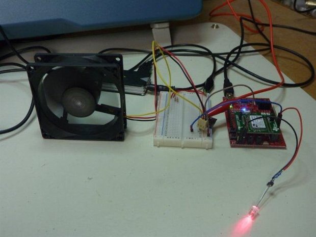
However I don't think this would impress the judges but it does show that I have some sort of idea of what's going on.
Out of the box SimpleLink WiFi CC3000 is most impressive!
"And all that Jazz!"
With the first pudding out of the way, it's now time to up the ante and add some sparkle to the project.
7th April
Energy Supply
Today I've rigged up a small solar panel,regulator and 12V SLA battery as a potential power power supply.
With a nice bright sunny day like today I was able to get about 200mA @ 14V to the battery to charge it.
The raw voltage level of the panel varied from around 16-20V. The regulator limits this to a max of 14V.
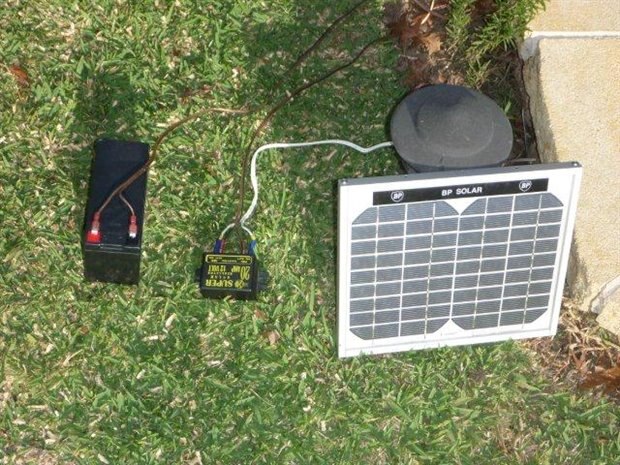
This is more than overkill for this application but it's a starting point.
A DC-DC converter is required to reduce the 12V from the SLA battery to the voltage required by the MSP430 and CC3000 (It could actually be less).
For efficiency a suitable TI Switching Power supply could be used.
TI WEBENCH provides a whole set of possible solutions based upon the specified requirements.
To accelerate the power availability, Super Capacitors and supporting circuits could also be added.
I have a couple of 100 Farad 2.5V working Super Capacitors with a maximum charge current of 75A.
The advantage is that Super Capacitors can be charged very quickly provided that the Thevenin equivalent resistance is very low as not to impede the charging process.
With such a low working voltage supporting circuitry is required to balance the charge distribution.
8th April
A ressurection!
The MSP430 range of microcontrollers uses very little power and to stay in that theme I thought any LCD panel should do so too.
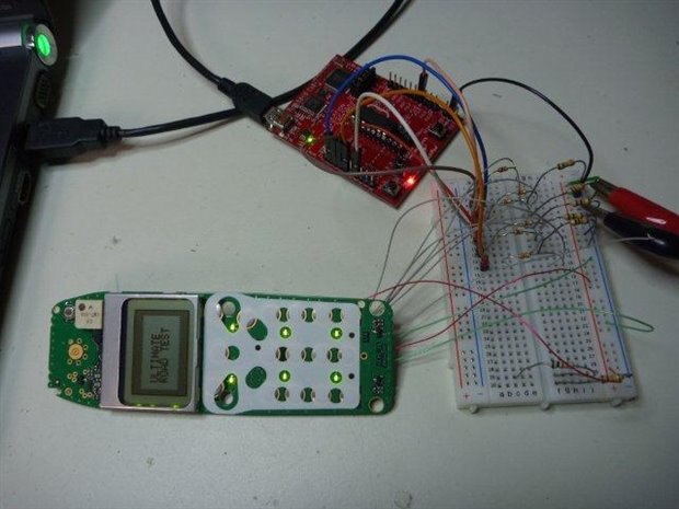
I've pulled out an old mobile phone to consider using it for this project.
My Moray I mean foray with MSP430 USI and SPI
This road test has required me to learn a fair bit about the MSP430 and fast!
To get the LCD screen working I must get the SPI interface working.
With the aid of my LaunchPad and 430Ware to the rescue, it didn't take too long to get something up and running.
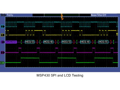
Pictured here is my attempt at generating the required signals.
Trace 2 SCLK (CPOL is irrelevant)
Trace 1 Data
Trace 3 -CS
Trace 4 Command/Data selection
There's also a -RESET pin that's driven and MISO signal but they're not shown above.
I've set the MSO to decode the data stream to confirm that it is correct.
11th April
"Getting high on LCD"
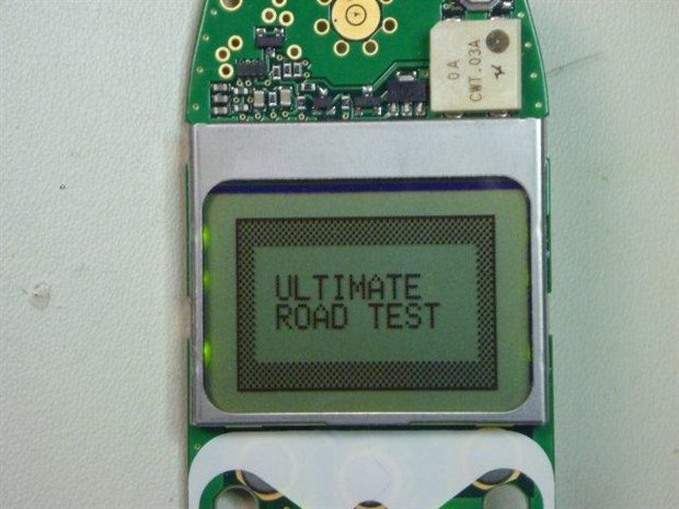
I've got the LCD working and have written a small driver to enable it to display some text and graphics.
Being a Graphic LCD, the host (MSP430) needs to generate the fonts and graphics. This all needs to be stored in the host's memory.
The functions written are:
drawLCDchar()
drawLCDstring()
These use a 5x7 font I created specfically for the LCD.
In addition to the abovementioned character functions, bit mapped graphics can be directly dumped to the LCD.
With the LCD working I can now get direct visual feedback from the MSP430.
Here's a picture of the setup. I am currently using some signal voltage dividers to down convert 3.6V to 3.3V logic levels.
These can be omitted later (by using VDD=3.3V).
12th April
"The EAGLE has landed - Part 2"
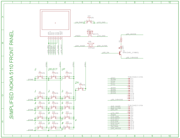
I have learned to use the EAGLE schematic capture to document the Nokia Front Panel connections. The procedure was foreign to me but once I got the jist of it it made sense. A bit like a German car where a lit LED indicates an off condition and the indicator stalk on the wrong side. I had quite a few occasions where I turned on the windscreen wipers by accident.
"What time is it?"
I have got the RTC working to toggle a seconds and minute LED from RTC interrupt events.
All I needed to do was to download the sample program from www.ti.com and modify it for use with the MSP430FRAM5739.
The adjustments are;
- XT1 clock oscillator initialisation.
- Remove no applicable code for RTC_B module.
- Adjust output pins used for LEDs.
- Toggle LED for minutes interrupt.
I shall post the source code when I learn how on this blog system.
14th April
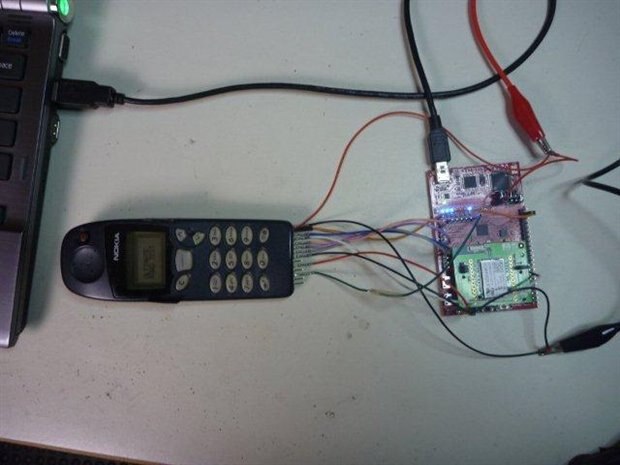
"Live Organ Transplants"
This is just a picture to show that the work done on the Launchpad has been transplanted to the Fraunchpad and all is operational.
15th April
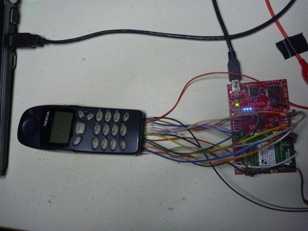
"Spreading your tentacles"
Look at all the wires now! Wow just so many!
The keypad has been fully connected up and is operational.
(!#$%- For some reason the blog system lost all my uploaded images. - I have worked out a method to restore them.)

