


16th April
After experiencing blog editor slowdown. I'd thought I'd break up the blog into separate sections to preserve the previous work.
Here are some pictures of the SimpleLink Wi-Fi CC3000 and its contents.
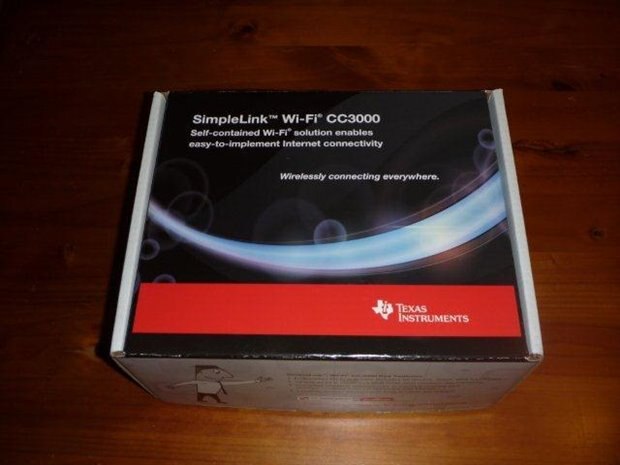
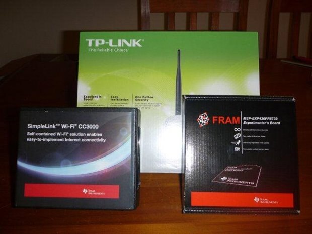

It comes with two SimpleLink Wi-Fi modules. One from LS Research and one from Murata. They are functionally identical.
I've currently using the LS Research module.
19th April
"The saga begins.."
I've completed my first video that demonstrates the use of CCS and MSP430WARE.
It has been recorded in 1024 x 768 resolution to ensure that the screen capture is legible.
If only the uploader won't error and let me use it.
It now has been posted. I just hope the re-encoding does not diminish its clarity.
If you look at the video, please note that additional connectors have been soldered to the FraunchPad. This was done to gain access to the I/O pins such as PJ1.0 and PJ1.1 that are not available on the standard connectors.
Also, you will also notice that external power has been connected. To do this look at the debug header. The VCC jumper between the Emulator and target has been disconnected with the VCC Target pin attached (and GND) connected to the external power.
20th April
"Beagle, We have separation"
To drive a 4 x 4 keyboard (or the Nokia 5110 keyboard) usually requires 8 I/O pins on a microcontroller when all columns and rows are assigned their own I/O pin.
Although working perfectly on the MSP430FR5739, I am rebuilding it on a slave MSP430G2553 to reduce the I/O requirement (on the MSP430FR5739).
Hopefully this will be a single pin. At worst it'll be 3 (2 input pins and an output pin).
I'll deem the Keyboard slave as a "Micro Input Terminal" as it will transmit keycodes to its host.
21st April
Here is the separated keyboard. For this testing I have temporarily used another 4x4 keyboard. It's wiring is not dissimilar to the Nokia 5110.
This MSP430G2553 has been programmed to output ASCII characters at 9600 baud (8 bits 1 no parity) .
The format output is ASCII SPACE (0x20) + <Row Index << 2> + <Column Index>.
This means the codes output are SPACE,A,B,C,D,E,F,G,H,I,J,K,L,M,N, and O.
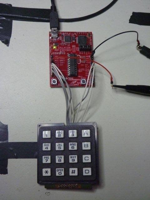
The idea is to interface it to the MSP430FR5739 using one of its serial ports thus reducing the required pin count to one.
I've attached the source code for those who are interested.
Here's just an updated shot showing conjoined Experimenter boards working together.
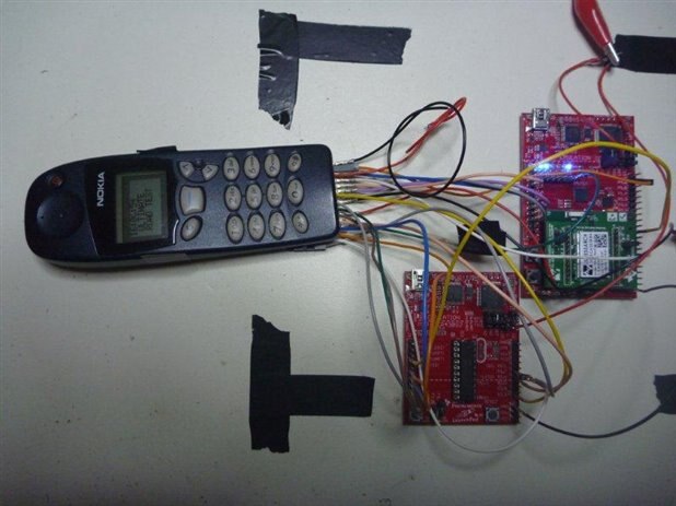
There are no LEDs lit on the lower board because it is using external power with the debug interface disconnected and off.
If you look at the LCD is shows that the Real Time Clock is working.
This is very important for data logging.

