


Hello Everybody!
Ready
So to begin with we all have the MSP430 FRAM Dev board and the CC3000 Simple Link WIFI link, all bundled up together.
We have access to all sorts of information and code examples in the MSP430ware database.
And we have a goal, make an awesome home automation project.
Set
Well what I would like to build and what actually makes any sense are two different things.
So whenever I go shopping I always forget something, I usually come home with everything except what I originally left the house to get.
Or I'll drop into the shops on the way home from work to pick up milk but not realise that I need coffee, sugar and bread.
What if I could grab my new smart phone and see in real time the levels of all of these basic commodities?
What if I got a notification on my phone when I ran out of something in the cupboard and it began to generate a virtual shopping list?
Sounds like a good idea to me..
GO!
I have an idea and I have some toys to play with, I guess I better get started then.
Cheers!
31st March : CC3000 Up And Running
Well I received my CC3300 Simple Link WIFI Kit a few days back and I have just had a chance today to have a play.
I figured that if this whole project is going to be based about this Simple Link then I had better get started and figure out what makes it tick.

I Have Two Networks
I am sure most people will be in the same boat here, I already have a home WIFI connection and I don't really want to turn it off. When I plugged in the Access Point that came with the CC3000 kit I had all sorts of trouble and the internet kept dropping out, turns out that my computer didnt really know where to look so it got confused.
The solution is really simple, all you need to do is give the new device a static IP but do not assign it a default gateway. As far as I understand the default gateway connects the internal network to the Internet, so if you force an IP address but don't give it a gateway it sits there happily networking away without even realising the Internet exists (remember how I understand it might be completely wrong).. Most people probably know how to do this, but I have made a little video just in case, it also gave me a chance to play a bit with video screen capture which I am sure will come in handy somewhere along the track.
Demo Application
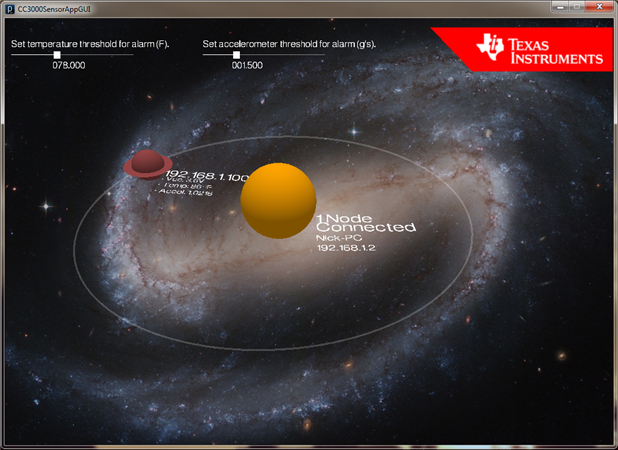
So the first thing to do is fire up the demo sensor application and see what happens.
Demo apps are nice, they show off some of the awesome features of the board and make you feel like you have done some work. The instruction in the getting started guide explain everything you need to know for this stage, they do not give a great deal of detail into what is actually happening though.. I guess they don't want to spoil the fun for later 
When you fire up the demo app GUI your FRAM board will start to collect temperature and accelerometer data right away. The CC3000 sends the data to your wireless access point, and the GUI displays the data using a cool space animation. Don't worry if it takes a while for your FRAM to start it's orbit, this is the AP attempting to resolve the FRAMs MAC address, for some it goes through all of the IP address from 192.168.1.1 to 192.168.1.101 before it guesses the right one. This morning I would have had no idea what "resolving a MAC address" meant (I probably still don't), but I think that is what is happening anyway..
Host Programming
That last part was easy right? Well this next part I found quite tricky. To make a kick ass wireless project you really need to have some control, this means whipping out Code Composer Studio and the CC3000 Host Programming Guide.
I found it quite daunting when I started looking at some libraries and the programming guide, there is quite a lot going on here to make this all work (I would hate to think what WIFI projects would be like without a "Simple" Link).
It is getting quite late over here in Aus so I will have to close up soon, I will just leave you with a teaser of what I have managed to far.
Basically the backbone of the project is going to be the CC3000 Simple Link Kit, this is just some hardware to facilitate sending collected data through walls. So my first step was to write some code for my FRAM board which would setup my WIFI link and let me send some data.
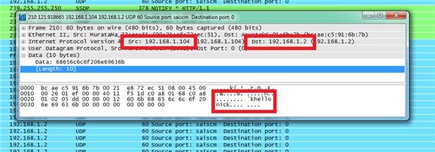
I decided I would make a totally original Hello Nick program (it is nothing like a Hello World program) it sends the string "hello nick" to the Acess Point once every second. I used Wireshark to check out what was going on on my WIFI network to make sure everything was working, the boring looking screenshot bellow was actually the highlight of my day (is that sad?).. As you can see, the CC3000 connected to my FRAM board (192.168.1.104) is sending the message "hello nick" to my wireless Access Point (192.168.1.2), wahoo!
Well that is what I did, in a couple of days I will explain how I did it, for anyone that is interested.. Are you excited? I am!
3rd April : How To WIFI
So like I said the other day I have my CC3000 up and running with all the control in the world. The configuration of the CC3000 can be split up into four main parts, and each of them split up into a number of other bits and so on and so forth. Eventually you end up with a huge mess of code, the only way I managed to get my head around it was to get some demo code and break it up into little bits. To have any chance you should make use of three handy libraries that TI have made available, the CC3000HostDriver library, the CC3000 SPI library and the Hyper Terminal Driver library I downloaded them all along with the CC3000 basic application from here.
Get Your CCS Project Ready
Now I did attempt to create my own CCS project and import the three libraries and include them in my own project but I could not get it to work, everything would compile but debug just refused to start (a job for another day).
To get around this I just imported the libraries and the basic WIFI application into my workspace and renamed the project to Bread&Butter. Then I deleted all the source code from the project and created my own main.c file to start off with. The fact that this worked makes me think that the problem is just a small linker setting or something. Your CCS project explorer should now look something like this, remember before you can build your project you must first build all of the libraries using the little hammer button above the project explorer.

The Four Basic Steps
So the setup process can really be split up into four parts three of these steps have to be done every time you turn on the CC3000 and want to connect to the Access Point. The different stages of completion of these four steps are monitored by a state machine with the following states.
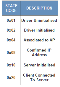
Step 1 : Initialise The Driver
The host driver library that we imported doesn't assume where the CC300 is plugged in, the initialisation basically gives it access to some peripherals (digital IOs and such) to control the CC3000.
SET STATE 0x02 (Driver Initialised)
Step 1.5 : First Time Config
This step only has to happen once, it will setup certain connection profiles and handle some other tasks I don't really understand yet. You can also set up different connection modes from here if you want, such as fast connect which will cause the CC3000 to always attempt to connect to the last used AP on power up. Once the first step is finished it will save a value into non volatile memory so it doesn't happen again (unless you force it to). You can use this to setup some intelligent connection modes to skip the next step (hence step 1.5).
Step 2 : Associate With the Action Point
This step will associate your CC3000 with your Action Point, I just force the CC3000 to use the SSID of my action point (TTTcBread&Butter0), like I mentioned before you can use smart connection profiles to skip this step.
SET STATE 0x04 (Associated to AP)
Step 3: Get an IP Address
This step allocates an IP address to your CC3000, you can either use DHCP and let the Action Point allocate your IP or you can use a static IP address. Once this is done check to make sure the IP address is OK, this step is mainly for DHCP if you are using a static IP it should always be OK.
SET STATE 0x08 (IP Address Confirmed)
Step 4 : Open a Socket
Again there are two choices here, you can go for the easy and fast UDP socket or take the time to set up a reliable TCP socket. Of course I went the easy route for now, a UDP socket or "connectionless" socket is super easy because all you do is open the socket and start throwing data at the action point. A TCP socket requires listening and accepting of connections and all it does is give you guaranteed data reception... OK that is pretty good I guess, but it is slower and in this case UDP works just fine.
SET STATE 0x10 (Server Initialised)
SET STATE 0x20 (Client Connected) ---- TCP ONLY
Step 5 : Send Data!
With a UDP socket sending data is really easy, just point it at the IP address of the Action Point and press send. I have not tried a TCP socket just yet, I will tell you about it when I get there.
That is enough for today I think.. I will start to explain some of the code that makes all this work in a couple of days.
Cheers!!
9th April : Off On a Tangent
I said I would start talking about code soon, but the last few days I have been working on getting my design up to scratch. My general idea is the real time measurement of the basic things you keep in the kitchen (bread, milk, sugar), I have decided that I will try a few different measurement techniques to keep the project interesting.
Weight Measurement : Milk & Bread
So the most obvious choice would be to use some load cells under everything and be done with it. That approach is kind of boring, also load cells are damn expensive! So I will measure the weight of just the milk and the bread for now, and think of something clever for everything else.
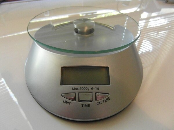
I have sourced two super cheap digital scales from ebay which I will rip apart and hack to do my bidding, I can not believe that I can get an entire digital scale (with a load cell inside) for about a quarter of the price of a single load cell.

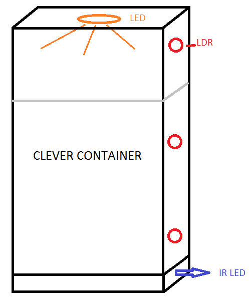
Clever Container Measurement : Sugar & Coffee
My clever containers will be used to measure things like sugar, coffee, flour etc etc. The idea is that I will use opaque Tupperware containers with 3-5 light dependant resistors down one side. An LED in the lid will illuminate the inside of the container, shining light on any LDRs above the level of the contents (and hopefully creating a cool effect). Now wires dangling off the container would cause all sorts of trouble, so each clever container will have a TI mcu (probably a launchpad) and an IR LED which it will use to communicate its content and level to a smart shelf. The smart shelf fitted with a bunch of IR receivers will then relay the information to my FRAM board with the CC3000..... Madness you say? Well, probably...
April 14th : Scavenging A Load Cell
Load me Up
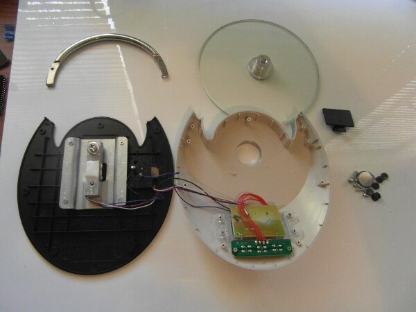
My first set of cheap scales arrived in the mail today and they actually look pretty nice, but all I want them for is the sweet load cell inside. Here are some photos of me taking it apart and extracting the juicy insides.
It Doesn't Suspect a Thing
Juicy Insides
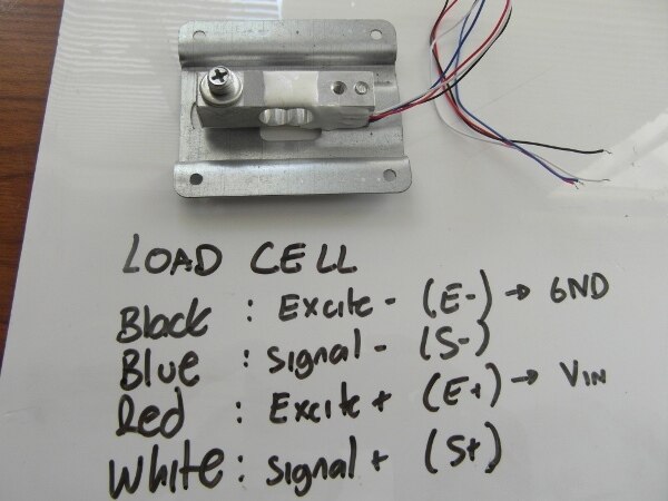
Load Cell Legend
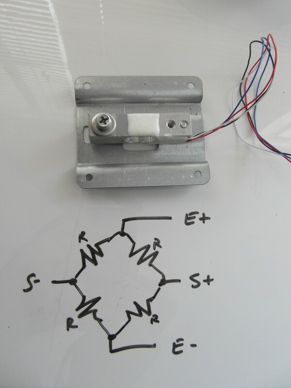
Load Cell Diagram
April 15th : More WIFI!
OK I am waiting for some more hardware to play with for my clever container, so I have decided to have another crack at getting a TCP socket working with the CC3000. Like I mentioned before TCP connections give you guaranteed data delivery, because the server needs to accept the clients request to connect you need some software on both the client (CC3000) side and the server (PC/Action Point) side.
The Demo Sensor Application used a TCP connection, but it set the CC3000 up as the server. It makes more sense to me to have the CC3000 set up as the client so the Demo Application didn't help me all that much. For the server side I decided to write my application using the QT framework, it's super easy to use and very powerful.
TCP Connections
I think the easiest way to understand a TCP connection is to visualise it, hopefully the picture I drew below makes as much sense to you as it does to me. All of you devices on the network have a whole lot of ports available, to connect two devices they each need to create a socket which will "plug into" a port. The TCP connection will then connect the sockets with a thread which allows communication between the two devices.
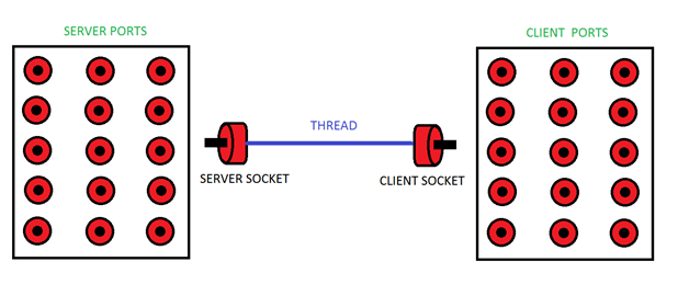
Server:
Step 1: Create a socket
Step 2: Bind the socket to the port and assign an IP
Step 3: Listen for incoming connection requests from clients.
Client:
Step 1: Create a socket
Step 2: Request connection to server
The Code!
Well my code is very similar to the Basic WiFi application demo, just better  . Well probably not but I have made a few changes that made sense to me, the unsolicited events are now handled in an interrupt that runs every 500ms rather than in random while loops all over the place. The CC3000 is setup as a client not a server, I also didn't bother with a lot of the smart config bits and pieces. I made it fairly flexible (I hope), you will find in the common.h file you can change all the network specific variables such as SSID, IP and port numbers, you can also choose to use UDP/TCP sockets or DHCP/static IP. Oh I also commented the bajeesus out of it..
All it does at the moment is send the string "hello nick" every second, but I'm sure you can think of something more exciting to use it for, anyway it is attached to the blog post and you can download it below.
April 22nd : LED Control
Polling Receive Function
I am still playing with the WIFI, I have been working on a little bit of control. Sending a string from the CC3000 client to the AP server is nice and all but I want to be able to control the clients from the server. I thought this would be as simple as just polling the receive function while the client was connected, I was wrong.. Turns out the receive function on the CC3000 is a blocking function and will sit and wait until some data is received, not particularly useful really. You could just constantly send data from the server, or you can use the select() function. The code below shows how you can poll the clients socket for available data using the select command.
The updated code is attached to the blog post below for your downloading pleasure.
timeval selTimeout;
fd_set readSet;

int getFromAP(unsigned char *buffer, long len){
          int recvd  = -1;

         //select will block for 500 microseconds
         selTimeout.tv_sec = 0;
         selTimeout.tv_usec = 500;

          //reset the fd_set structure
          FD_ZERO(&readSet);
          FD_SET(clientSocket, &readSet);

          //poll the client for receive events
          select(clientSocket+1, &readSet, NULL, NULL, &selTimeout);

          //if data available then receive
          if(FD_ISSET(clientSocket, &readSet)){
                    blinkRX();
                    recvd = recv(clientSocket, buffer, len, 0);
          }

          return recvd;
}
RGB LED Demo
To test and demonstrate my receive function and my GUI I hooked up an RGB LED to three PWM outputs. If you watch the video in full screen you can see that when I turn on the MSP430 board the first 5 LEDs come on to show that the board is initialised and connected, when the connection is established the state is updated at the bottom of my GUI. The sixth and seventh LEDs are the transmit and receive LEDs respectively, they blinks for half a second when any data is transmitted or received. The eighth blinking LED is the heartbeat LED, the CC3000 sends a "." every 500ms as a keep alive byte and the LED lets me know it is still going.
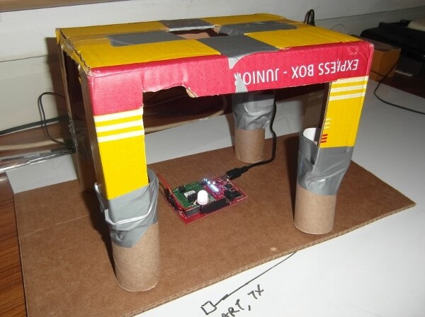
Camera Stand
Fancy camera stand? I think not! Cardboard box and toilet rolls are all you need to make yourself something to hold your camera.. The camera usually sits in the square hole at the top, but in this photo the camera is in my hands.
Top Comments