


The whole CCS not finding things has been narrowed down to the machine as a whole. It either needs a holiday or a kick/complete reinstall. Not a fun task either way, so in the meantime there will be a quick switch to mspgcc. This should at least provide a little bit of help while I try out the recent delivery.
This week was special, it was the delivery of the last few (Hopefully!) parts. TI need a round of applause here for their fine courier selection. To go from getting the despatch email at 05:01 to having a package in your hands that afternoon is amazing. Lets just ignore the fact that the courier may well have been using time travel at this point as getting the stuff across the sea in that time is a bit unlikely…
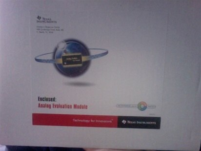
Cue exciting box photos.
First up is the light component of the project, the LED driver. Based on the requirements, the TPS61042EVM was chosen. In the ever so slightly misleading box you will find three things, the evaluation module (actually really tiny), the manual for the EVM and a datasheet for the part. Yes, this particular EVM contains printed copies of the documents. There is a lot of discussion going on about paper copies of documents such as this, a quick search will show you a few on element14, but personally, with parts like this is a great help. On the times you are setting up a EVM to use and finding you are rapidly running out of space, a laptop can be a little inconvenient, where as a paper document you can easily move around or lie one top of things without risk of damaging them is rather useful.
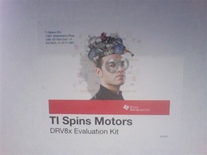
Second up is the motor driver, in this instance it is the DRV8805EVM. Chosen for its stepper motor capability, in particular the step function and direction control, this IC should make the driving of the blind much easier. In the box is the PCB holding the driver IC and a MSP430 to control it. Should you just be after testing the driver, the MCU can be bypassed so you can control the device with your own signals. Also present is a handful of test points so you can monitor exactly what is going on. The box contains a USB lead so you can program the onboard MSP430 with your applications or the demo applications. Sadly this kit does not include any datasheets like the LED driver kit, they are all available online however.
Last up is the networking portion. Although this project uses WiFi for the control part, it is designed to be able to control different rooms. Doing this with WiFi would be a little impractical, however there is a nice little protocol designed for this kind of task, ZigBee. This protocol has a few application profiles which demonstrate what it is good for use in, one of these is a Home Automation application. Taken from Wikipedia on the subject, typical uses include “Home Entertainment and Control — Home automation, smart lighting, advanced temperature control, safety and security, movies and music”, so essentially what we are aiming for. To make it even more suitable, TI have the CC2530 ZigBee Network Processor Mini Development Kit. In the box is a coordinator module and two end devices, each using the CC2530 IC to handle the ZigBee network and a MSP430 to control that and hold your application.
A few notes about these, watch out for the motor kit as it is liable to get hot. Its what happens with that much current! For the ZigBee kit, users in Japan need to pay attention to the local laws. The kit contains a useful leaflet about the requirements for using it (Suitably protected lab etc), make sure you pay attention. Finally, the LED driver kit contains its own LEDs which unsurprisingly can get a bit bright. You may want to take some precautions around this like a filter over it to dim it slightly. The user guide also warns that the device may get a little hot (60C+), so be careful with that. Your own fault etc if you accidentally cook a finger 

The first run!
While it has been seen that the MSP430 chips work well, I seem to be plagued by compiler issues, whether it be the IDE having issues, the compiler just not liking files, gmake being difficult or just Windows being massively unstable. I would try it through Ubuntu, but that doesn’t like the USB drivers for some reason. Odd udev rules I think.
With the application of another processor though, it is possible to get the new kit up and running. In this case, using an Arduino to generate a PWM signal (possibly dirty and not at all following the datasheet advice), the LED driver can be controlled, and it does exactly what is needed. Time to try and work out the rough values for the levels of light.
The motor controller isn’t so easy. The supplied demo software works well and controls the chip in an appropriate manner. The problem is with the motor. Seems I have bipolar ones and not what I though they were. Quick trip to ebay to sort that I think.
The ZigBee kit is for testing tomorrow. Time to see if I can fix the mspgcc sample makefile to at least get small test programs running. I fear the main project source will require CCS to compile properly, but I’m confident any issues will be simple tweaks so for now can remain as it is on github. With any luck the smaller individual components and protocol will work, it will just be a case of them compiling when put together (wlan.h was a common error when the compiler was working, the rest usually worked). We shall see what happens after a few kicks, more swearing at it and a different approach. In the event the compiler wasn’t MIA, I am sure the project would work well on hardware, any electronics issues will be down to minor mistakes by the software guy.

