


Progress!
While waiting for my boards to arrive I've been prototyping/testing and I've been busy preparing the 'final' product. To charge the batteries I'm going to use a TPS61165TPS61165 White LED driver, because it is meant to be used as a step-up converter with current output. To prototype some functionality I received the evaluation boardevaluation board . The configuration on the board features three white LEDs, see usage below:
Input power: 4.8V, 0.87A. Output power: 10V,0.36A
One of the features I wanted to test was the protection of the output FETs; to do this I added a Zener and a resistor in the circuit (see previous posts), which limits the output voltage when the load is removed; in my charger design the load is switched on and off by the bq2002T NiMH charger IC. This load is not switched directly, but by using 2 FETs. To keep these small I used low-voltage FETs (20V), but when the TPS61165EVM-283TPS61165EVM-283 switches off the output voltage can reach levels of 40V... Smoking FETs are not my design goal, so I wanted to test my circuit before soldering everythin on my boards.
After some modifications, this is what the evaluation board looked like:
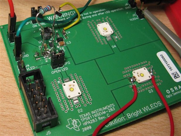
One LED bypassed (to lower output voltage), and some solder-FU to patch the reference circuit
Luckily this passed the test; removing the load gave a peak voltage of 10.5V. Margin enough!
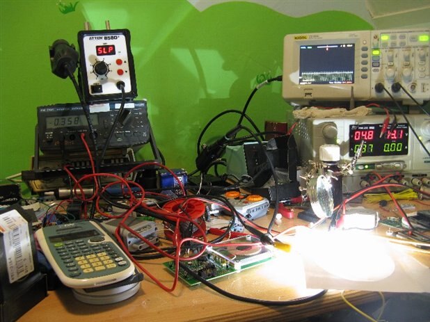
Testing the complete link:
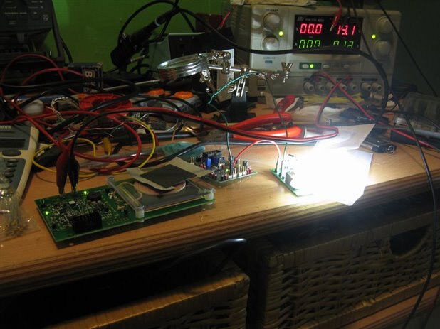
Qi transmitter, receiver, LED board
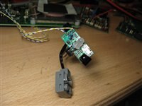
Preparing the LEGO train
The LEGO train I'm going to build needs a LEGO Power Functions receiver. I'm working on an open source receiver ( http://www.hackvandedam.nl/openpowerfunctions ), and I'm going to use this receiver in the LEGO train. The advantage is that I can reprogram the receiver to start driving when the battery is nearly empty, and to stop when the coil is detected. I hope to get this finished in time; meanwhile, here's a look at the receiver board, with some modifications:
To make some room in the battery box to fit the Qi receiver, I have to convert from AA batteries to AAA batteries (and not use sleeves, those will eat up the space again). When it comes to mechanics, I'm a real simplist, so I used cardboard and pushpins as bridge between the contact terminals and the batteries!
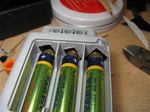
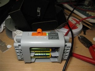
And it works (see green LED on top of battery box)!
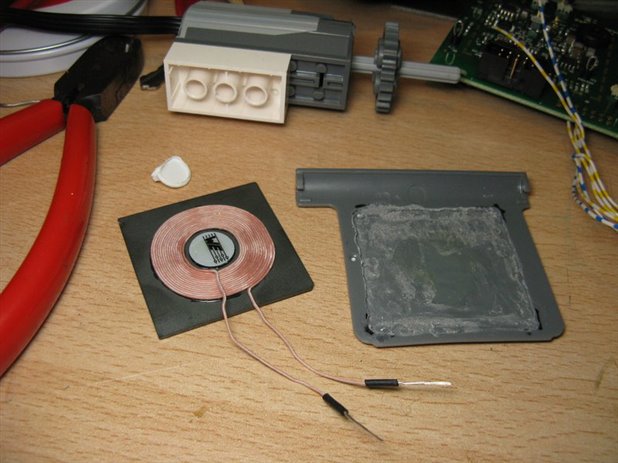
The last thing I did today was glueing a Qi receiving coil in the battery box; although the train uses a coil under the train, I'm going to make a separate box with a built-in receiver:
That's it for now, I hope the PCB's will arrive somewhere around Tuesday, I'll keep you posted!