element14 Community
element14 Community
    Register Log In
  • Site
  • Search
  • Log In Register
  • Community Hub
    Community Hub
    • What's New on element14
    • Feedback and Support
    • Benefits of Membership
    • Personal Blogs
    • Members Area
    • Achievement Levels
  • Learn
    Learn
    • Ask an Expert
    • eBooks
    • element14 presents
    • Learning Center
    • Tech Spotlight
    • STEM Academy
    • Webinars, Training and Events
    • Learning Groups
  • Technologies
    Technologies
    • 3D Printing
    • FPGA
    • Industrial Automation
    • Internet of Things
    • Power & Energy
    • Sensors
    • Technology Groups
  • Challenges & Projects
    Challenges & Projects
    • Design Challenges
    • element14 presents Projects
    • Project14
    • Arduino Projects
    • Raspberry Pi Projects
    • Project Groups
  • Products
    Products
    • Arduino
    • Avnet & Tria Boards Community
    • Dev Tools
    • Manufacturers
    • Multicomp Pro
    • Product Groups
    • Raspberry Pi
    • RoadTests & Reviews
  • About Us
  • Store
    Store
    • Visit Your Store
    • Choose another store...
      • Europe
      •  Austria (German)
      •  Belgium (Dutch, French)
      •  Bulgaria (Bulgarian)
      •  Czech Republic (Czech)
      •  Denmark (Danish)
      •  Estonia (Estonian)
      •  Finland (Finnish)
      •  France (French)
      •  Germany (German)
      •  Hungary (Hungarian)
      •  Ireland
      •  Israel
      •  Italy (Italian)
      •  Latvia (Latvian)
      •  
      •  Lithuania (Lithuanian)
      •  Netherlands (Dutch)
      •  Norway (Norwegian)
      •  Poland (Polish)
      •  Portugal (Portuguese)
      •  Romania (Romanian)
      •  Russia (Russian)
      •  Slovakia (Slovak)
      •  Slovenia (Slovenian)
      •  Spain (Spanish)
      •  Sweden (Swedish)
      •  Switzerland(German, French)
      •  Turkey (Turkish)
      •  United Kingdom
      • Asia Pacific
      •  Australia
      •  China
      •  Hong Kong
      •  India
      • Japan
      •  Korea (Korean)
      •  Malaysia
      •  New Zealand
      •  Philippines
      •  Singapore
      •  Taiwan
      •  Thailand (Thai)
      • Vietnam
      • Americas
      •  Brazil (Portuguese)
      •  Canada
      •  Mexico (Spanish)
      •  United States
      Can't find the country/region you're looking for? Visit our export site or find a local distributor.
  • Translate
  • Profile
  • Settings
Imagine a World Without Cords
  • Challenges & Projects
  • Design Challenges
  • Imagine a World Without Cords
  • More
  • Cancel
Imagine a World Without Cords
Blog Start of BeagleBone QiCape
  • Blog
  • Forum
  • Documents
  • Files
  • Mentions
  • Sub-Groups
  • Tags
  • More
  • Cancel
  • New
  • Share
  • More
  • Cancel
Group Actions
  • Group RSS
  • More
  • Cancel
Engagement
  • Author Author: vsluiter
  • Date Created: 25 Oct 2012 4:12 PM Date Created
  • Views 1904 views
  • Likes 1 like
  • Comments 9 comments
  • wireless_power
  • beagle
  • wireless_power_challenge
  • wireless_power_charging
  • qi_standard
  • BeagleBone
  • qi
  • wp_challenge_one
Related
Recommended

Start of BeagleBone QiCape

vsluiter
vsluiter
25 Oct 2012

Ok, ok..... I just overdid myself. I became VERY enthousiastic when Shawn told about the BeagleBone BeagleBone Cape. I think these new Linux-based boards are very attractive to tinkering, understanding embedded processing and making internet-connected... things!


I started creating this design, and I've come quite far in the progress. The last bit takes a bit too much of my time though since I should be spending time on the RoadTest design, and in my private live I've had some 'turbulent days' which boils down to taking a bit more time for myself. I couldn't seem to get to the point of making the decisions to finish the design. I hope my design can be a starting point, and after the RoadTest I can take a bit of time at my own pace to finish it, or maybe someone else has had a better idea yet...


image

Line of thought

What I wanted to do is ensure you can use the BeagleBone on Qi, and on a battery.The Qi receiver can supply up to 1A, so it is safe to let it power the board (which takes ~500mA max according to the documentation) and charge a LiPo battery. I've looked into LiPo charging solutions, but found out a simpler way; the BeagleBone carries a power management IC that already incorporates a LiPo charger in the Power Management IC (PMIC)!

Now we're getting into more troublesome terrain; can you use the LiPo battery connected to the PMIC to keep the BeagleBone going when no Qi power is available? The answer is... yes and no. Yes, you can run the BeagleBone from a LiPo battery at the battery connection; No, you can't use USB host or other IO that needs 5V. The easy way out is to say: do not use 5V IO / USB in combination with Qi. I found that a bit crude, and limiting the possibilities of the BeagleBone. My solution is to incorporate a few switches in the design to achieve the following functionality:

  • When using Qi power: power the board from Qi, and let the PMIC charge the LiPo battery.
  • When Qi power is gone: disconnect Qi from the 5V supply input of the BeagleBone, disconnect the battery from the PMIC, and connect it to a boost converter (I used the WEBENCH tool to design one; really comfortable!) to boost the battery voltage to 5V, and run the BeagleBone 5V USB INCLUSIVE from the LiPo battery

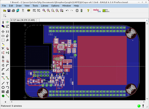
Sounds easy, became a bit complicated. But I got the major part in a schematic and layout.


ToDo

OK, so what are you looking at when opening the design files? I tried to solve the circuit described above by using the available signals, and some FETs and BJTs. I could have used a small microcontroller for that, it might still be wise to do so, but it's easier to understand and less error prone when done with hardware only (my opinion, I know others think different). Also, I know the MSP430 series can go in REALLY low power, but you have to design your software to go to IDLE / STOP modes. I have no experience in that field.

Which points are still open in this design?

  • Finish the last bit of routing
  • No on-off switch for the battery. Do you need one on the PCB? Easiest to use is a toggle switch, but I wanted the layout to be as low as possible to just glue the RxCoil of Qi to the Cape. Use a microcontroller after all, and a small push-button? Or is that overkill?
  • What connector to use? Different batteries use different connectors, so I now just used plated holes to solder wires. Is that OK?
  • Use a jumper (low profile / horizontal mounting to keep a flat surface) to use a dummy 10k resistor as NTC, when the LIPO pack does not have its own NTC
  • Place LEDs for debugging / power indication:
    • Qi present
    • LIPO voltage
    • 5V present
  • All resistors are now 0402. I have no problem with that size, but maybe others do
  • Review functionality. I did this by thinking, and not yet by testing. Maybe others have different / better ideas / see errors I overlooked.
  • Last but not least: do we need an under voltage lockout (UVLO)? When the battery is connected and supplying the board it is being drained - fast. An UVLO should protect the battery, and shut down the supply to the BeagleBone. Some battery manufacturers include it in the cell, or do all manufacturers do this? I have no experience in this, so please comment...

Credits

Thanks to the BeagleBone documentation and the Adafruit Proto Cape I was able to comprehend the BeagleBone and have a good starting point for the layout. A small comment on the Adafruit board: their 'keepouts' for connectors on the BeagleBone are on the top instead of at the bottom, and are a few tenths of mm off. Good starting point anyway...


What can you do for QiCape?

I saw several people with ideas for a QiCape. Although I do not have the time needed to finish this very soon, I'd hate to see my efforts wasted. If you're looking for a starting point: see the files below (Eagle). And please let me know your concerns / thoughts, I'm very curious what you're thinking about it!


What can the QiCape do for you?

It's a board file and a schematic using the Qi receiver, including all values and ordering codes (in the Qi part). Please re-use it!

Attachments:
imageliion 5V out v3.pdf
QiCape-v0.1_board_and_schematic.zip
  • Sign in to reply
Parents
  • johnsocm
    johnsocm over 13 years ago

    Hello Victor,


    I am a little confused on the BeagleBone Cape you have designed. It seems that the big red box is for the wireless eval kit. When I designed a BeagleBone Cape the wireless eval kit did not fit in between the headers of the cape. I had to do a complete redesign.


    Also, when you did the WebBench Designer did you just perform a simple 3.7V min/4.2V max input and a 5.0V output with a 1.0A charge rate Buck Boost? Or did you change anything as far as efficiency, footprint size, or BOM cost, resistor sizes to establish a better design. It seems that the design is just the design that web bench creates automatically, which isn't a bad thing either. But for this design space is definitely a concern.


    I am using a battery management system because there are a lot of details to charge a battery under lower power and when efficiency is a must. Here are some things that a simple buck boost will not perform.


    Stage 1: CC: Apply charging current to the battery, until the voltage limit per cell is reached.


    Stage 2: Balance: Reduce the charging current (or cycle the charging on and off to reduce the average current) while the State Of Charge of individual cells is balanced by a balancing circuit, until the battery is balanced.


    Stage 3: CV: Apply a voltage equal to the maximum cell voltage times the number of cells in series to the battery, as the current gradually declines asymptotically towards 0, until the current is below a set threshold of about 3% of initial constant charge current.


    Thank you very much for your design and help with the community but I am really confused on how almost all the routing is done because the Qi portion hasn't even been started, unless you plan on just sticking the eval kit on top of the Cape. I guess I would like to see more details.

    • Cancel
    • Vote Up 0 Vote Down
    • Sign in to reply
    • More
    • Cancel
  • vsluiter
    vsluiter over 13 years ago in reply to johnsocm

    Hello John,

    Thanks for taking a look at my design, great that my effort is not wasted image

    I annotated the layout view below:

    image

    • The big red box is a placeholder for the 37x37mm receiver coil, not the complete eval kit. You can see the Qi receiver circuit in the upper left corner.
    • Yes and No. I did just a simple 3.7 to 4.2 V in to 5V/ 1A out calculation, but then changed the coil to a Wuerth type that was lower than the default type so the height of the components would not exceed 2-3mm -> not much higher than the receiver coil.
    • I'm also using a battery management system, but the one that is already present on the beaglebone. See http://beagleboard.org/static/beaglebone/latest/Docs/Hardware/BONE_SRM.pdf page 30. This controls the current, because a single cell is used no balancing circuit is necessary, and the TPS65217B also deals with the last step. The output of this IC is found on P6.
      • When Qi is available this is how power goes: Qi->5V_VDD BeagleBone->TPS65217B->Battery charger->Battery on connector P6
      • When no Qi is available: Battery->Boost converter->5V_VDD BeagleBone, battery detached from charger circuit
    • The trick in this design is to switch al available power sources.

    Please,please let me know when it is still unclear; I'll be glad to help you.

    • Cancel
    • Vote Up 0 Vote Down
    • Sign in to reply
    • More
    • Cancel
  • johnsocm
    johnsocm over 13 years ago in reply to vsluiter

    Hello Victor,


    I wasn't using your design, I just wanted clarification of your work for others and myself. For me and many others it would be more work to adapt a design that remains unfinished rather than to start from scratch. I do indeed appreciate your work and what you have done but this will not help me in my design.


    I am very confused on how you plan on receiving power with the coil mounted on the Qi cape. The power will not transmit that far, as the distance is too great for a transmitter to go through a BeagleBone plus the hight of the headers and then the Qi Cape.


    Can you clarify how this would work? We're your intentions of the transmitter being on the top or the BeagleBone upside down?


    Thank you,


    Chad

    • Cancel
    • Vote Up 0 Vote Down
    • Sign in to reply
    • More
    • Cancel
  • johnsocm
    johnsocm over 13 years ago in reply to vsluiter

    One more thing, where would the components fit of the receiver board?

    We need at least two layers just for the bq51013 via's. So if the board is already filled with the buck boost and receiver coil plane there would not be enough room left for the rest of the components.

    I do thank you for your work but if anyone was to use this, these questions came up immediately when reviewing your design.


    I will post my design to show you what I mean if you would like.


    Chad

    • Cancel
    • Vote Up 0 Vote Down
    • Sign in to reply
    • More
    • Cancel
  • vsluiter
    vsluiter over 13 years ago in reply to johnsocm

    Hello Chad,

    I intended to place the BeagleBone upside down, and place the complete Qi receiver on the Cape. In the layout I posted all components for both the boost converter and the Qi receiver are already placed.

    See the crude 3D plot below: Dark green: beagle bone. Light green: QiCape. Red: rx coil from Wuerth.

    image


    So, yes, you'd have to place the beagle bone upside down on a charging pad. Depending on the battery size you might squeeze it between the boards, or pack it at the opposite side from the receiver.

    The PCB I designed is a 2-layer design, with all SMD on the top layer to facilitate debugging.

    Please open the design in Eagle, both the layout and the schematics are attached, you can see what I've done.


    I'm very curious to your approach, I do sometimes tend to over-design....

    • Cancel
    • Vote Up 0 Vote Down
    • Sign in to reply
    • More
    • Cancel
  • johnsocm
    johnsocm over 13 years ago in reply to vsluiter

    Ok thank you.


    I just wanted to see others approaches as well and this clarified a bit for everyone I am sure!


    I have been on vacation so I can only view all of this from my phone as well as type, but I have my receiver coil attached to the bottom of the Beagle bone and I plan on making a case to house the Beagle bone ad coil. Then one can just put the beaglebone in the case, plug in the Qi Cape into the headers, plug in the battery and be done.


    I will post my design when I get back from vacation. My board layout is extremely different than yours as well as the shape, but basically the same design with a standalone battery management system so this can be adapted to other devices if needed.


    It is definitely great to design with others and see what we all come up with.

    Chad

    • Cancel
    • Vote Up 0 Vote Down
    • Sign in to reply
    • More
    • Cancel
Comment
  • johnsocm
    johnsocm over 13 years ago in reply to vsluiter

    Ok thank you.


    I just wanted to see others approaches as well and this clarified a bit for everyone I am sure!


    I have been on vacation so I can only view all of this from my phone as well as type, but I have my receiver coil attached to the bottom of the Beagle bone and I plan on making a case to house the Beagle bone ad coil. Then one can just put the beaglebone in the case, plug in the Qi Cape into the headers, plug in the battery and be done.


    I will post my design when I get back from vacation. My board layout is extremely different than yours as well as the shape, but basically the same design with a standalone battery management system so this can be adapted to other devices if needed.


    It is definitely great to design with others and see what we all come up with.

    Chad

    • Cancel
    • Vote Up 0 Vote Down
    • Sign in to reply
    • More
    • Cancel
Children
No Data
element14 Community

element14 is the first online community specifically for engineers. Connect with your peers and get expert answers to your questions.

  • Members
  • Learn
  • Technologies
  • Challenges & Projects
  • Products
  • Store
  • About Us
  • Feedback & Support
  • FAQs
  • Terms of Use
  • Privacy Policy
  • Legal and Copyright Notices
  • Sitemap
  • Cookies

An Avnet Company © 2025 Premier Farnell Limited. All Rights Reserved.

Premier Farnell Ltd, registered in England and Wales (no 00876412), registered office: Farnell House, Forge Lane, Leeds LS12 2NE.

ICP 备案号 10220084.

Follow element14

  • X
  • Facebook
  • linkedin
  • YouTube