element14 Community
element14 Community
    Register Log In
  • Site
  • Search
  • Log In Register
  • About Us
  • Community Hub
    Community Hub
    • What's New on element14
    • Feedback and Support
    • Benefits of Membership
    • Personal Blogs
    • Members Area
    • Achievement Levels
  • Learn
    Learn
    • Ask an Expert
    • eBooks
    • element14 presents
    • Learning Center
    • Tech Spotlight
    • STEM Academy
    • Webinars, Training and Events
    • Learning Groups
  • Technologies
    Technologies
    • 3D Printing
    • FPGA
    • Industrial Automation
    • Internet of Things
    • Power & Energy
    • Sensors
    • Technology Groups
  • Challenges & Projects
    Challenges & Projects
    • Design Challenges
    • element14 presents Projects
    • Project14
    • Arduino Projects
    • Raspberry Pi Projects
    • Project Groups
  • Products
    Products
    • Arduino
    • Avnet Boards Community
    • Dev Tools
    • Manufacturers
    • Multicomp Pro
    • Product Groups
    • Raspberry Pi
    • RoadTests & Reviews
  • Store
    Store
    • Visit Your Store
    • Choose another store...
      • Europe
      •  Austria (German)
      •  Belgium (Dutch, French)
      •  Bulgaria (Bulgarian)
      •  Czech Republic (Czech)
      •  Denmark (Danish)
      •  Estonia (Estonian)
      •  Finland (Finnish)
      •  France (French)
      •  Germany (German)
      •  Hungary (Hungarian)
      •  Ireland
      •  Israel
      •  Italy (Italian)
      •  Latvia (Latvian)
      •  
      •  Lithuania (Lithuanian)
      •  Netherlands (Dutch)
      •  Norway (Norwegian)
      •  Poland (Polish)
      •  Portugal (Portuguese)
      •  Romania (Romanian)
      •  Russia (Russian)
      •  Slovakia (Slovak)
      •  Slovenia (Slovenian)
      •  Spain (Spanish)
      •  Sweden (Swedish)
      •  Switzerland(German, French)
      •  Turkey (Turkish)
      •  United Kingdom
      • Asia Pacific
      •  Australia
      •  China
      •  Hong Kong
      •  India
      •  Korea (Korean)
      •  Malaysia
      •  New Zealand
      •  Philippines
      •  Singapore
      •  Taiwan
      •  Thailand (Thai)
      • Americas
      •  Brazil (Portuguese)
      •  Canada
      •  Mexico (Spanish)
      •  United States
      Can't find the country/region you're looking for? Visit our export site or find a local distributor.
  • Translate
  • Profile
  • Settings
Wireless Power - Beyond the Phone
  • Challenges & Projects
  • Design Challenges
  • Wireless Power - Beyond the Phone
  • More
  • Cancel
Wireless Power - Beyond the Phone
Blog Waterproofing marine equipment - 04 - Efficiency Tests
  • Blog
  • Forum
  • Documents
  • Files
  • Events
  • Mentions
  • Sub-Groups
  • Tags
  • More
  • Cancel
  • New
  • Share
  • More
  • Cancel
Group Actions
  • Group RSS
  • More
  • Cancel
Engagement
  • Author Author: ForcisConnect
  • Date Created: 3 Apr 2014 10:02 AM Date Created
  • Views 654 views
  • Likes 2 likes
  • Comments 4 comments
  • waterproofing_marine_equipment
  • beyond_the_phone
Related
Recommended

Waterproofing marine equipment - 04 - Efficiency Tests

ForcisConnect
ForcisConnect
3 Apr 2014

This last week I have been busy doing some tests to the wireless power kit.


The first thing I wanted to measure was the efficiency. I decided to measure efficiency from 0 to 1.2 Amps of output current in steps o 100mA.  Obviously efficiency is going to change with the distance between the coils, so I measured it with the following coil separations: 1, 3.5, 9.5 and 11mm. These strange numbers result from the combination of the following:


  • 1mm: It’s the thickness of the plastic mount to which the receiver coil is attached. I wasn’t able to accurately measuring it, so I took Hendrik Lipkas word for it.
  • 3.5mm: The receiver plastic mount + the acrylic base of 2.5mm
  • 9.5mm: I 3d printed two small 5mm stand-offs for testing.  Add 1 on top of the prior 3.5 mm and you get 9.5mm
  • 11: Removed the transparent plate and used both stand-offs. 5+5+1 = 11 J


Equipment Setup and Test Conditions:


I connected the power transmitter to a regulated DC power supply at 5.0 V. Voltage was measured at the transmitter input pins, as voltage drop across the cable becomes significant with up to 2 Amps current. As the power supply also displays the delivered current, no additional equipment was needed on the transmitter side.

On the receivers side I connected my electronic load (see previous post) to Vout and Gnd (J3 and J2) of the receiver board. In parallel to that I connected a Voltmeter. This has to be done on the receiver pins for the same reason as with the transmitter. Another multimeter measured current flowing through the load. Finally, the electronic load was powered by another independent power supply (12V) 


There are various user settings on the receiver that can influence its behavior:

  • EN1 and EN2: These control the operation mode of the receiver, setting the priority of wireless or wired power, OTG mode etc (añadir más detalles).

In my tests, both are set to low

  • Ilim: The receiver board has an overcurrent protection circuit build in. It allows us, by selecting the right value for a resistance, to set the max output current. In the EVM, we can either select a fixed 110Ohm resistor or a potentiometer through a jumper. I used the potentiometer in its minimum position, measuring 198 Ohm between JP6-ADJ and GND position in order to get as much current as possible out of the device.
  • TS: The TS jumper allows us to enable the thermal shutdown function of the receiver. If a NTC resistor is connected on J5, this jumper allows us to enable the function and regulate the threshold temperature. In our case, the jumper was set to disable the function.


The test procedure was quite simple: Set the output current to the desired value, write down the values, increase current by 0.1A, write down the values, increase....

And here are the results:

Fullscreen 4251.contentimage_52547.html Download
<html><head><title>Jive SBS</title></head>
<body><font face="arial,helvetica,sans-serif">
<b>Error</b><br><font size="-1">
An general error occurred while processing your request.
</font></font></body></html>


These graphs show very clearly how the efficiency is affected by coil separation. They also resemble the  ones found in the data sheets. I have attached the excel file if someone wants to take a closer look at the numbers.


The next thing on my testing list was to test different core materials. Although I did not expect them to influence the result (unless you use metal, in that case the Foreign object detection (FOD) should stop the transfer), I wanted to confirm it.


As core materials I chose medium density fiberboard (MDF) and a solid 3d-printed PLA sheet. Both were 3mm thick. 


Fullscreen 2117.contentimage_52548.html Download
<html><head><title>Jive SBS</title></head>
<body><font face="arial,helvetica,sans-serif">
<b>Error</b><br><font size="-1">
An general error occurred while processing your request.
</font></font></body></html>


Looking at the results I don’t really think there is an influence at all. Sure, some points are not the same, but I rather think this is due to the difficulty of getting the exact same alignment in both test series.

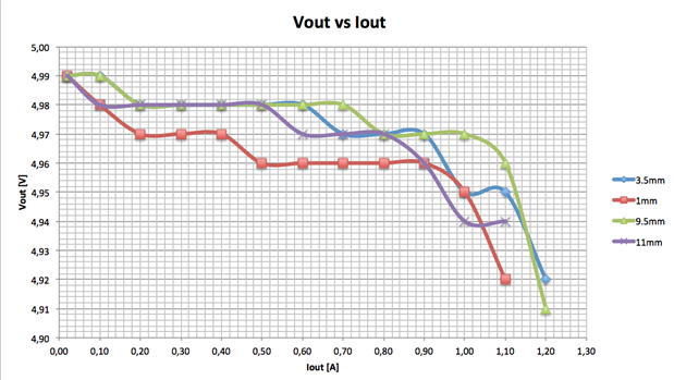
Another interesting figure is Vout vs Iout. TI claims that the output voltage stays above 4.95V for a load current of up to 1.0 A. And it certainly does. Nevertheless it’s curious that voltage drops quicker with only 1mm distance. Maybe there was a little bit of lateral displacement while I took the measurements. But it doesn’t really matter.


image


For next week I want to take a closer look with the scope at the different signals present on the board: Communication, Rectified voltage, Modulation signals etc. Most of them are available on the datasheet, but it’s always nice to be able to reproduce them.

  • Sign in to reply

Top Comments

  • mcb1
    mcb1 over 11 years ago +1
    jeez guys I'm starting to wonder about the other measurements now .. (the electrical ones) .. This is really good material for anyone wanting to design or use wireless charging. Its helped me to make decisions…
Parents
  • hlipka
    hlipka over 11 years ago

    Thanks for this evaluation - the graphs look much nicer than my ugly tables image Btw - you wre wrong in relying on me  that the base is 1 mm thick. I did just estimate that too. But your post just prodded me to really measure it. Just add something of known dimension to it (I used 1 mm wire), and use calipers. Now I know its 2 mm thick...

    Regarding the last graph: the trasnmitter changes its transmit power with reagrd to the diatanxce of the coils, and the power needed by the receiver. So the magnetic coupling of the coils will affect that. I too saw that a distance of 1 mm (or 2, for that matter ;-) affects the performance.

    Btw: should the third distance not be 8.5 mm ( 3.5 + 5 )?

    • Cancel
    • Vote Up 0 Vote Down
    • Sign in to reply
    • More
    • Cancel
Comment
  • hlipka
    hlipka over 11 years ago

    Thanks for this evaluation - the graphs look much nicer than my ugly tables image Btw - you wre wrong in relying on me  that the base is 1 mm thick. I did just estimate that too. But your post just prodded me to really measure it. Just add something of known dimension to it (I used 1 mm wire), and use calipers. Now I know its 2 mm thick...

    Regarding the last graph: the trasnmitter changes its transmit power with reagrd to the diatanxce of the coils, and the power needed by the receiver. So the magnetic coupling of the coils will affect that. I too saw that a distance of 1 mm (or 2, for that matter ;-) affects the performance.

    Btw: should the third distance not be 8.5 mm ( 3.5 + 5 )?

    • Cancel
    • Vote Up 0 Vote Down
    • Sign in to reply
    • More
    • Cancel
Children
  • ForcisConnect
    ForcisConnect over 11 years ago in reply to hlipka

    You are totally right! 3.5 +5 equals 8.5. Don't know what I was thinking when I wrote it wrong...three times! XD

    • Cancel
    • Vote Up 0 Vote Down
    • Sign in to reply
    • More
    • Cancel
  • hlipka
    hlipka over 11 years ago in reply to ForcisConnect

    But OTOH, since the 3.5 should be a 4.5 in reality (2+2.5), your 9.5 is correct again image

    • Cancel
    • Vote Up 0 Vote Down
    • Sign in to reply
    • More
    • Cancel
element14 Community

element14 is the first online community specifically for engineers. Connect with your peers and get expert answers to your questions.

  • Members
  • Learn
  • Technologies
  • Challenges & Projects
  • Products
  • Store
  • About Us
  • Feedback & Support
  • FAQs
  • Terms of Use
  • Privacy Policy
  • Legal and Copyright Notices
  • Sitemap
  • Cookies

An Avnet Company © 2025 Premier Farnell Limited. All Rights Reserved.

Premier Farnell Ltd, registered in England and Wales (no 00876412), registered office: Farnell House, Forge Lane, Leeds LS12 2NE.

ICP 备案号 10220084.

Follow element14

  • X
  • Facebook
  • linkedin
  • YouTube