


Receiver Assembly and Tests:
As I promised in my last post this week I have been assembling and testing my receiver boards. And yes, that I was able to test something means they work!!!
At first I was quite scared of this moment. Placing all the tiny components, soldering them and then hoping for it to work… wow, that seemed like a really big challenge. But, if I have been taught something while becoming an engineer it is to break big problems down into smaller ones.
So let’s take a look at each one of them:
1. How am I going to get the right amount of solder paste onto the board??? Well, as probably most of you know, solder stencils are the solution.


2. How am I going to place all the tiny components???
Patience tweezers and a steady hand are your best friends here. And it isn’t that difficult, as the components stick to the solder paste, making it only necessary to move them a little bit around to have them nicely placed. And they don’t need to be perfectly aligned or placed either; the surface tension of the solder paste will drag them into place while reflowing.
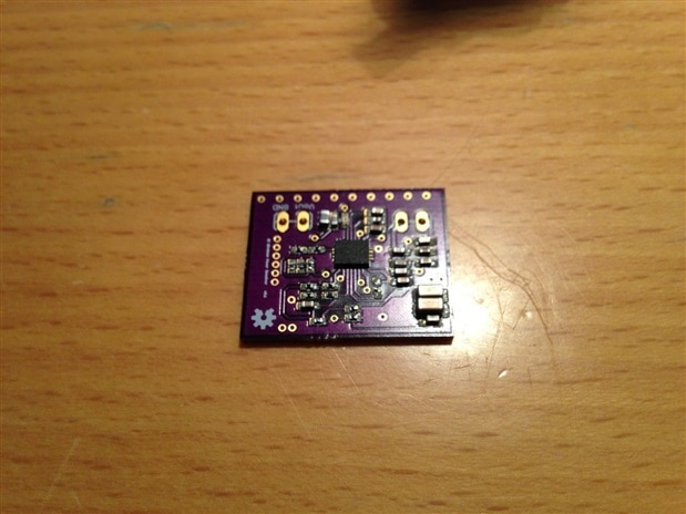
(Sorry for the picture, it's a little bit out of focus)
3. How am I going to solder it??
The technique used is called reflow soldering. You can do it in an oven or on a hot plate. I decided to the oven way. On the Internet there are a lot of tutorials and videos explaining how to modify an oven and add temperature control to it. I must admit that I tried to build a reflow controller by myself, but gave up after a lot of fighting with a MAX31855 thermocouple amplifier that was giving random readings. I may continue working on it when I have some more spare time. So, how did I do it? Just place the board in the oven, turn it on (max heat) and look at the board until it has completely reflowed. Turn the oven off, open the lid and let it cool down. Not the most professional way to do it, but it certainly works.
4. Once it’s cooled down, solder the coils, place it on a transmitter, cross your fingers and turn it on!
As usually, the first board didn’t work. I started looking at it, trying to find the error. I did found the following:
- I had not connected the thermal pad of the IC to GND. Such a stupid mistake.
- While ordering the components for the board, I got the footprint of a .47uF cap wrong, and ordered a 0402 where a 0603 was needed. I tried getting the 0402 to fit the footprint of the 0603, but it lifted while reflowing, so connecting it afterwards was a big mess. I immediately ordered the right sized caps for the second board.
- While assembling the second board I then noticed that, again, where a 66.6kOhm was needed I had ordered a 66.6Ohm one. I couldn’t believe it. This resistor was needed for the NTC temperature sensing part, that could be disabled with two 20k resistors that I already had, as I did not want to pay another 9€ shipping for a strip of ten resistors.
So I tried assembling a second one, and it finally worked!! Yuhu!
As I explained in my Wireless Power receiver blog post my board can work with both the bq50050B and bq50013B ICs. The second board mounts the bq50013B, while the third one uses the bq50050B, battery charger IC.
Tests:
Bq51013B:
I performed one test series with the same setup as last time, but only taking measurements at one distance, with the receiver coil on top of the acrylic plate.


The results look quite good and are close enough to the ones measured on the evaluatin board. If you take a look at the Vout vs Iout graph you can clearly recognize a linear drop with current, so I’m sure I’m measuring a voltage drop in a cable or contact somewhere in my measurement setup. This will probably be also the reason for the smaller performance at higher loads. But it’s not a big deal, so I won’t repeat the measurements.
BQ51050B:
I attached the charger to a battery I had laying around that was completely empty with a voltage of 2.1V. The circuit started to charge the battery immediately and after more or less one hour (I forgot to measure the time) it stopped. The battery had 4.15 Volts. So this also seems to work.
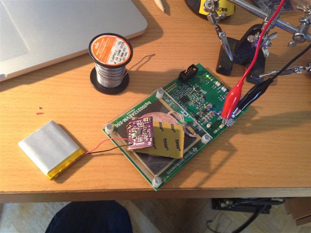
After I had the battery charger working, it was time to mount the battery, the PCB and the buck-boost converter together to get my desired power management unit.
And this is the result:


The result is very compact, with a total footprint of 10x48x34 mm. With it, I now have a 3.3V supply from my battery, can charge it anytime with a Qi-charger and it is ready to be integrated into any current and/or future project. In the next revision of the board I will probably merge the two into a single board, avoiding the two wires connecting them. I'm also considering the option of adding a 5V voltage rail to make it polyvalent.
After this huge success I will try my luck with the transmitter board. Let’s hope it also turns out so well!!
-

n.donthi@prothelis.de
-
Cancel
-
Vote Up
0
Vote Down
-
-
Sign in to reply
-
More
-
Cancel
Comment-

n.donthi@prothelis.de
-
Cancel
-
Vote Up
0
Vote Down
-
-
Sign in to reply
-
More
-
Cancel
Children