


In the Mini IIe project, I need video output. The Rev 1 shown in the project video relied on the analog video circuit from the IIgs. So I copied and pasted it from the IIgs schematic. (Well, in KiCad 5, you had to copy the file and then edit the schematic to remove what you did not want. But ... the same idea.) The positive to this approach is that I had a ready-to-go circuit. The downside is that it is still wholly analog AND not compatible with all digital capture devices.
Apple II Video
 : "The Apple II Circuit Description" by W. Gayler
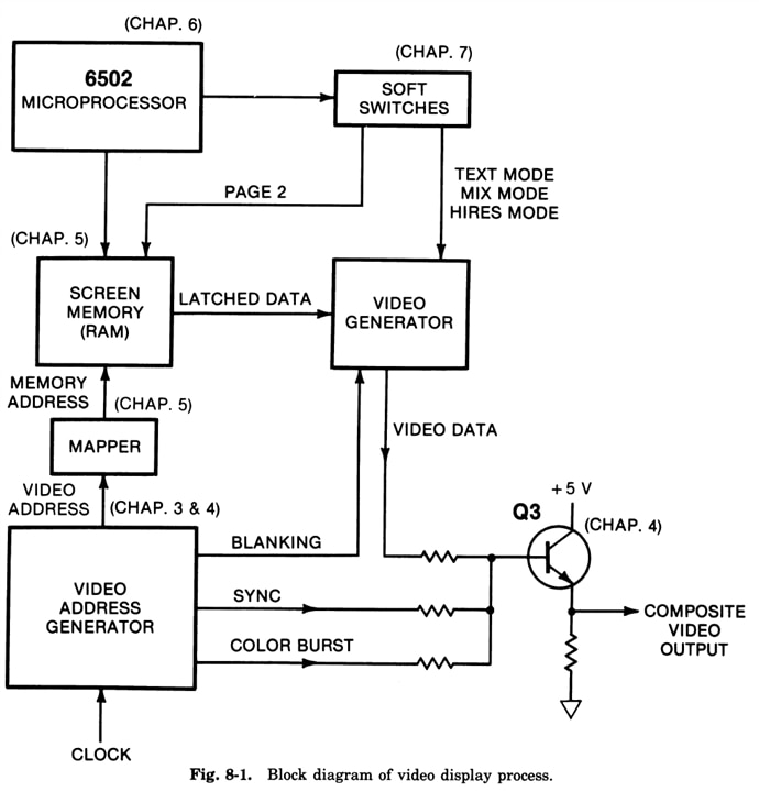
Apple II video is famous, or infamous, for how Steve Wozniak designed it. The block diagram above is from a book on the original Apple II. The fundamental video system is the same in all Apple IIs, except the IIgs. Adding 80 column support changes some memory areas, but the other modes are the same. The video generator circuit is the logic that creates a digital video bitstream. In that block diagram, it is labeled "Video Data" while the Mega-II (and IIe) call the same signal SERVID.
NTSC Color (Brief Primer)
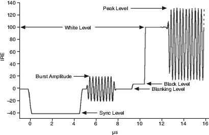
(: Video Levels from NI)
In NTSC video, there is a sync pulse for the start of a frame, a voltage level to set black, a voltage level to set white, and then luminance (brightness) information. For a black and white display, you can use a waveform that is either ON or OFF in that area to make dots appear on a TV screen (or monitor.) If a 3.58 MHz signal, called Color Burst, is added before the black level, the receiver knows the rest of the waveform contains color information. In addition, the luminance now includes a modulated signal on analog video generators where the modulation's phase difference from the Color Burst adds chrominance (Color) information. This clever "hack" is how color could co-exist on the already widely used "B&W" standard. And it worked great from the 1960s until the early 2000s when broadcasters phased out analog TV.
: "The Apple II Circuit Description" by W. Gayler
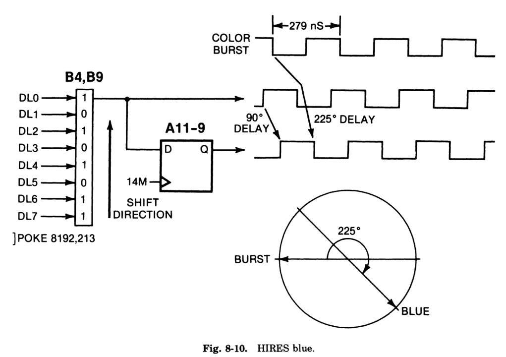
However, it created a potential problem for digital computers like the Apple II. Wozniak didn't design an analog system or add another oscillator to generate the chrominance. Instead, the Apple II's all digital video generator uses a shift register in the video generation block to shift the "luma" signal's phase, causing a dot to change color. Since color is phase-related, the receiver cannot always distinguish between two luminance "points." So, depending on the colors picked you might either end up with a big white dot or a slight rainbow effect as the receiver struggles to interpret the all-digital waveform. (The behavior also depends on which video mode the Apple II is operating in.)
In the original Apple IIe and the Mega-II, there is a digital signal called "Serial Video" or SERVID. The video has a bitstream of luminance information, with the appropriate phase shifts. Combining that signal with a sync pulse and color burst creates an "analog" composite video signal with color.
Mega-II's SERVID Signals
Since I do not want an analog output, we need to find a way to convert the digital bitstream of the Mega-II into a modern digital video signal. The Mega-II outputs a handful of video-related signals. There are four RGBx signals, which might seem like one too many. However, they are not discrete color channels! Instead, they are a slower parallel copy of SERVID.
The IIgs's VGC uses those four RGBx signals, the system clocks, and Mega-II's SYNC horizontal SYNC signal to create 12-bit binary red, green, and blue values. The rest of the video circuit converts those digital values into analog and adds color burst information when the video mode requires it. The VGC also creates a vertical blanking signal.
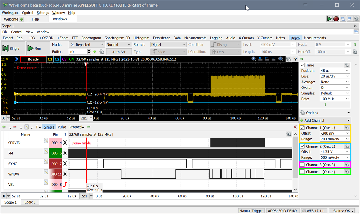 : Top waveform is composite analog, and the bottom is digital creating it
After extensive measurements with an Analog Discovery Pro, we determined that it should be possible for us to take in the SERVID signal, SYNC, and either the 7 MHz or 14 MHz clocks to build video frames line-by-line.
The question is, then what do we do next? Well, we frame buffer the signal with a microcontroller. Since getting this signal in at a few MHz will be time-critical, it looks like another use-case for the RP2040, which means there are three options to consider: VGA, USB, or HDMI.
VGA
Andy's Game Guy video shares some commonalities with the Mini IIe project. It is re-packing retro technology into a different form factor while using the Pi Pico (or RP2040) as glue. The main difference is that he made his project physically bigger, and I am making mine smaller! His project takes analog video and converts it into VGA, which uses an RP2040. Then for HDMI, he's using a no-name VGA to HDMI adapter. For the Mini IIe, I want a more integrated solution, so while this is an optional path, I'd rather consider it a backup plan.
USB
Regardless of the option we use, they will require using a frame buffer. Fortunately, the tinyUSB library already has support for Video and Audio devices. So it would be possible just to put a micro-USB port on the back, plug it into a computer, and use something like OBS or VLC to "capture" the output. The primary benefit here is that it uses very little extra hardware. The downside is that it requires a PC to be useful.
HDMI
I like the idea of using USB for testing (and streaming.) However, in my latest vision for the Mini IIe project, I want to connect it to an HDMI-capable monitor (or TV). So for HDMI, I think we will use an ITE Tech 6613. It's an HDMI transmitter that can take in digital RGB (or luminance) signals that output to HDMI. It is the same chip used in the Open Source Scan Converter project. Getting the chip is another story. (And is for another time.) We will likely have to rely on something like the OSSC project's code on how to control it since I do not have an NDA for the (whole) datasheet.
But, that is getting a little too far ahead.
What about the RP2040's DVI Sock?
People have pointed me to one project called the "DVI Sock." It's a combination of hardware and RP2040 PIO code that outputs a DVI-compatible signal from the RP2040. While this benefits from creating a signal that HDMI receivers can use, it is missing one key feature: audio. There's no well-established method for getting audio and DVI into an HDMI TV.
If you know of one, let me know below!
(Current) Video Plan
My video plan uses an RP2040 to ingest the SERVID and SYNC signals from the Mega-II, buffer it in RAM, and then output via USB. (Andy's latest video has me thinking this is the right direction.) I have already fabricated an RP2040 to HDMI PCB for testing. The primary goal with this board is to test the ITE 6613's modes and registers.
My thinking is that since the bitstream is well defined, we should be able to reconstruct the analog picture from SERVID. My concern is that color artifacts may not survive. 
With all of that said, I am still open to other ideas! For example, what else should I consider for converting the Apple II video bitstream to something modern?
-

lukazi
-
Cancel
-
Vote Up
0
Vote Down
-
-
Sign in to reply
-
More
-
Cancel
-

baldengineer
in reply to lukazi
-
Cancel
-
Vote Up
0
Vote Down
-
-
Sign in to reply
-
More
-
Cancel
Comment-

baldengineer
in reply to lukazi
-
Cancel
-
Vote Up
0
Vote Down
-
-
Sign in to reply
-
More
-
Cancel
Children