Hi all,
With winter coming there is one project that stands out that needs to be done before it fully settles in. Remote start/stop of the generator in PAW.
The Problem
During the winter months, I will have to run the generator from time to time. So far, I do not have data as to how often I will have to run it, but I am planning on needing to probably once a day, or once every couple of days until I get all 16 panels up in the correct spot. The problem is having to walk down to PAW to turn the generator on and off. Not a big deal when it's dry, but when it's muddy/raining/snowing, and or in the dark, it can be a real drag.
The second part of the problem is running the generator in an enclosed space. Having the doors on PAW closed so rain or wildlife does not get in.
Requirements
- Remote start and stop of the generator
- Signal must travel of IP to utilize the CAT5 cable I have already installed, rather than using any of those conductors for direct signals.
- Display State of Charge, DC system Voltage, real-time watts from generator (also tells me if generator is on or off), real-time watts from PV
- LED indicator of relay states
- Additional start/stop capability inside of PAW
The Generator
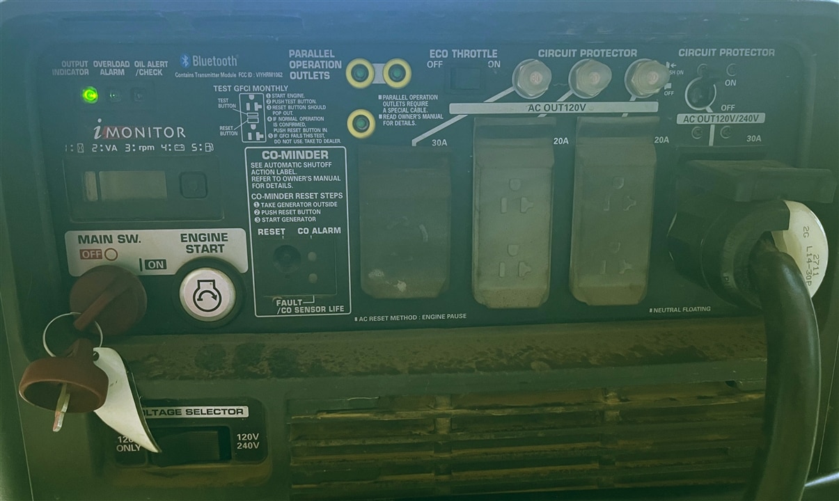
It is a Honda EU7000is gasoline generator with built-in Bluetooth functions. PAW is too far from the house for bluetooth to my phone by itself, but if the doors are closed, it is sealed in a steel box and the signal is definitely not getting through.


There are kits for remote starting this model of generator and they start around $400 for the non bluetooth solutions. From what I can see these kits all have a long wire that connects the remote to the generator.
This means that there is a way to interrupt the signal in the generator to start and stop it.
Aaaaand, I have already found it.

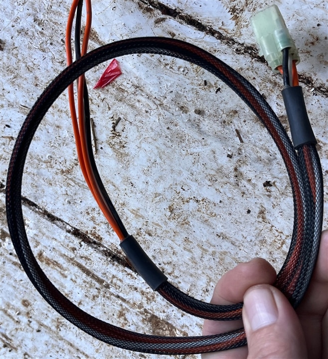
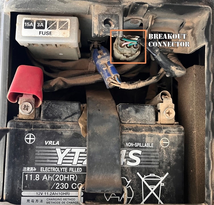
Below the control panel on the generator, there is a connector that is connected to the key switch and pushbutton on the control panel. Someone has made a breakout cable that will connect to this connector giving me four wires. Two of them shorted together will close the circuit for the key switch, and the other two are momentary for the pushbutton. I have already ordered, received, and tested this breakout. It works great just by touching them together.

The second part of this is running the generator inside PAW with the doors closed.
Venting & Ducting
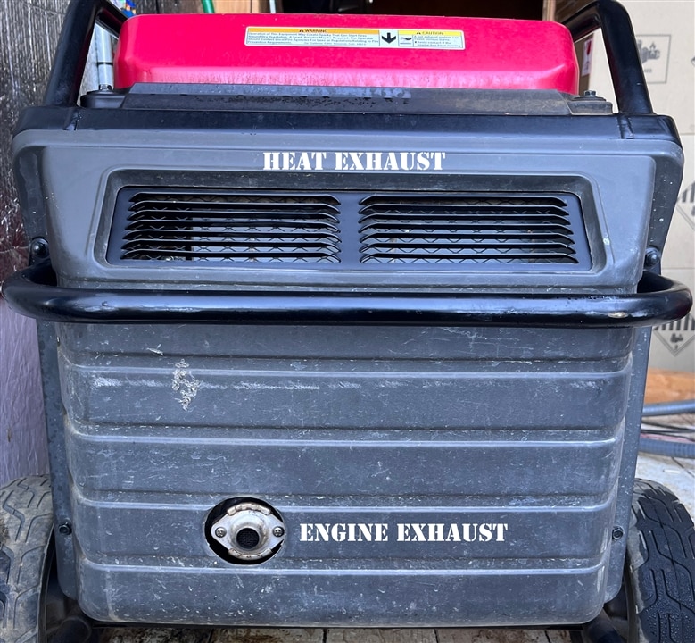
The generator exhaust has a small diameter hole with a flange. For this, I think all I need to do is fabricate a flange that is the same size and hole pattern, and then weld a small tube onto that so I can attach a flexible duct to it. I will then run this outside through a hole in the side of PAW.
The generator also has a large vent on the back of the unit to vent heat. I am not sure what the mechanism is, but it pushes quite a bit of air out of this vent.

The Proposed Solution
My current plan is to have two identical units that have a start button, stop button, and four, four digit seven segment LED displays. The displays will show the State of Charge in percentage, DC system voltage in volts, Total generator output in Watts, and Total PV output in Watts. One unit will be in the house next to the front door, and one will be in PAW.
I am putting a second unit inside PAW, because that breakout cable disables the front panel controls on the generator. I need to have control inside of PAW.
I will use an Arduino NANO IOT 33 microcontroller since they are available, have WiFi, and plenty of IO. With this, I can read the state of the buttons, and access MQTT data wirelessly for the displays. It will also enable signal over IP which is one of the requirements.
The layout of the units will be the same, same buttons and displays, but the PAW unit will also need to have two relays to close the connections on the breakout cable. Pushing the buttons on the PAW unit will directly control the relays. Pushing buttons on the house unit will send a signal to the PAW unit to control the relays.
I have used these 7-segment displays before with the MAX7221 LED display driver and they work pretty well together, though I have not run two of them together on the same MCU. Since they are SPI I should be able to do this. I am going to order them today so I can do some testing.
I have a couple of IOT33's here and tried to connect to the CerboGX data unit via modbusTCP, and it worked, but only for a couple of minutes before the MCU locked up. I have checked my code for memory leaks and tried a different IOT33 to no avail. I can't find anything on forums that is similar. I ran several tests to see if it was time-based, or if the CerboGX was throttling queries. It seems that it's random when the MCU locks up. I set it at a 10-second delay between queries and ran it until it stopped and logged the number of cycles. It ranges between 27 and 208 cycles before locking up.
My backup plan to this if I cant figure it out is to have an existing Raspberry Pi poll the data from the CerboGX and send it to MQTT, and then query MQTT from the Arduino IOT33's. It adds another level of complexity, but it should be reliable.
My plan for the exhaust venting is to fabricate a sheet metal housing that will go over that vent, and then use standard heating duct from the hardware store to guide the heat exhaust out through another hole in the side of PAW.
It's looking like there will be a video of this build. So keep an eye out!
But, before I really get started, what do you all think? Sound like a good plan? Any other ideas?
Thanks!
-Kaleb
