


Time to Make Beautiful Music with Mark!
Playing saxophone in a local Big Band and making instrumental YouTube videos took up a good deal of Mark Donners' time when he was younger. Playing the right note is one thing, but getting it properly in tune is another. Instrument tuners and phone apps can certainly help, but neither is particularly convenient when somebody is holding a saxophone and trying to keep an eye on a tiny display at the same time.
And, as Mark points out, the passing years haven't made tiny displays any more appealing.
His answer was suitably difficult to miss: make the tuner much, much bigger.
The resulting project combines an ESP32 DevKit V1, an INMP441 MEMS microphone and a strip of WS2812 addressable RGB LEDs with an unusual display made from glass building blocks. Instead of concentrating on a little needle or a handful of pixels, the musician gets a large illuminated indication of whether the note is flat, sharp or in tune.
"Not just any tuner... this time we're going to build an instrument tuner."
Although Mark built and programmed it with woodwind instruments in mind, including tenor, alto and soprano saxophone and B-flat clarinet, there is nothing about the basic principle that limits it to those instruments. As Mark suggests, the same approach could be adapted into a guitar tuner or used for other instruments where a highly visible tuning indicator would be useful.
The Electronics
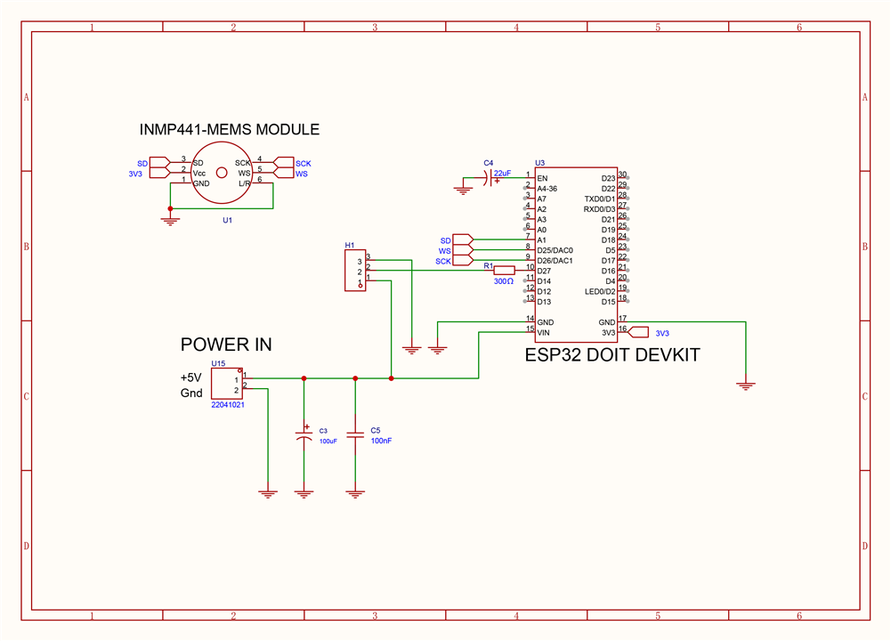
The electronics are deliberately fairly modest. At the centre is an ESP32 DOIT DevKit, chosen in typically practical fashion because Mark already had several of them and they are inexpensive. Another ESP32 could be substituted, although the GPIO assignments in the firmware would then need checking and possibly changing.
"You could use actually any ESP32, but you might have to change the setup of the pins in your software."
The audio input comes from an INMP441 MEMS microphone module using the ESP32's I2S peripheral. In Mark's configuration the microphone is powered from 3.3 V, its L/R pin is pulled to ground to select the left channel, SD is connected to GPIO33, SCK to GPIO26 and WS to GPIO25. The LED data output meanwhile comes from GPIO27 through a 300Ω series resistor. The WS2812 strip itself is powered from the 5 V supply.
The distinction between the microphone's 3.3 V supply and the LED strip's 5 V supply is worth paying attention to when recreating the wiring. The finished circuit might have relatively few components, but getting the supplies and I2S connections right is important. The project schematic provides the clearest reference for checking the physical build before power is applied.
Some basic supply conditioning is provided too. The BOM specifies a 100 nF TDK FG18X7R1H104KNT00 X7R capacitor rated at 50 V, Farnell order code 3772381, together with a 100 µF Wurth Elektronik 860130273002 aluminium electrolytic capacitor rated at 10 V. The 300Ω LED data resistor is a Vishay MBA02040C3000FRP00 metal-film component rated at 0.4 W with a 1% tolerance.
There is also a 22 µF capacitor associated with the ESP32 enable line. The BOM specifies Wurth Elektronik part 860160272001, a 22 µF, 10 V radial electrolytic rated for 4,000 hours at 105°C. Mark added this after considering a problem that can crop up while programming some ESP32 boards.
"If you have problems programming, put a capacitor to ground and the enable."
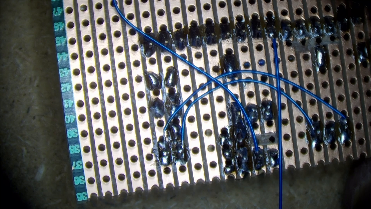
The board itself is built on prototyping PCB. Mark first positions the ESP32 sockets and supporting components, trims the PCB to the required dimensions and removes copper where necessary before completing the point-to-point wiring. This is a compact practical build rather than an elaborate custom PCB, which also makes it reasonably approachable to reproduce.
One construction lesson is particularly worth retaining. Mark notes that component leads and wires should ideally be cut before soldering so that the subsequent mechanical action does not put unnecessary stress on a completed solder joint. He admits that he did not follow his own advice everywhere on this build because the alternative was easier, but it is nevertheless a useful practice for a more permanent version.
A Tuner You Can See Across the Room
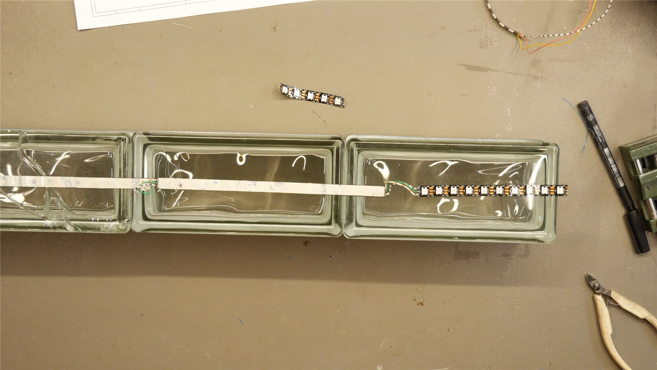
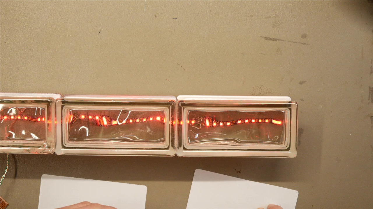
The electronics solve the measurement problem, but the distinctive part of the project is the display. Mark had wanted an excuse to experiment with the sort of translucent glass building blocks commonly found in walls and decorative architectural features. Stacking several of them creates something considerably larger than a conventional instrument tuner.
A WS2812 addressable LED strip runs behind the blocks. Recovering the strip from a previous build also gave Mark an opportunity to reuse hardware rather than buying another length merely for the project.
The glass proved less forgiving.
"I dropped it while recording... Things happen, sometimes for the best, sometimes for the worst. But we'll make the best of it."
One of the blocks cracked during filming, reducing the original collection of three pristine blocks to two plus a damaged one. Rather than abandoning the display, Mark glued the blocks together and carried on. Once assembled and illuminated, the damage was far less significant than it first appeared.
Simply placing visible WS2812 LEDs behind the glass did leave another aesthetic problem. It produced a line of distinct bright emitters rather than the broad coloured areas Mark wanted. In his words, it looked rather like a "giant flux capacitor". Enter the diffusers.
Mark 3D printed thin PLA sheets, around 0.3 mm thick, and placed them between the LED strips and the glass. The material spreads the light sufficiently to turn a conspicuous string of LEDs into a much more even glowing panel. Builders without a 3D printer need not abandon the idea either, as a suitable piece of paper can provide a simple alternative diffuser.
The firmware is currently configured for 42 WS2812 pixels, using the Adafruit NeoPixel library, with the LED brightness set to 80. The whole strip changes colour together: red means the detected note is too low, green means it is considered in tune and orange means it is too high.
Turning Sound into Pitch
There is more going on inside the ESP32 than the simplicity of the display suggests. This is not merely code looking for the loudest frequency bin and choosing a colour.
The firmware samples the INMP441 at 16 kHz and uses a 1,024-sample analysis window. Each new analysis retains half of the previous buffer before adding another 512 samples, giving 50% overlap between windows. At 16 kHz, that 512-sample hop corresponds to 32 ms, helping the display react quickly enough for live playing rather than feeling heavily damped or delayed.
#define SAMPLE_RATE 16000
#define BUFFER_SIZE 1024
#define HOP_SIZE 512

#define MIN_FREQUENCY 80.0f
#define MAX_FREQUENCY 2200.0f
The configured 80 Hz to 2.2 kHz detection range was selected to cover the intended saxophones and B-flat clarinet while retaining some headroom for higher registers and altissimo playing.
Before analysing pitch, the ESP32 calculates the average of the audio buffer and subtracts it from every sample to remove its DC component. At the same time it calculates the RMS amplitude. Signals below the configured RMS threshold are treated as silence, which prevents random low-level noise from repeatedly changing the giant display.
Pitch detection uses a Normalized Square Difference Function, or NSDF, an approach related in principle to the McLeod Pitch Method. Rather than looking only at spectral magnitude, the routine searches the sampled waveform for strong periodicity. For each possible lag, it measures the relationship between samples and their delayed counterparts, normalising that measurement against their energies.
float denominator =
  energy1 + energy2;

if (denominator > 0.0f) {
  nsdf[tau] =
    2.0f * acf / denominator;
}
The firmware then hunts for local maxima in the NSDF. An important detail is that it deliberately prefers the first sufficiently strong periodic peak instead of blindly accepting whichever peak happens to be largest. The threshold for that initial selection is 0.72.
This is useful with instruments such as saxophones and clarinets because their waveforms contain plenty of harmonic information. A pitch detector can otherwise become attracted to a harmonic and report a note an octave away from the intended fundamental.
Mark tackles that problem a second time with explicit octave validation. Having calculated a potential fundamental, the firmware checks whether there is sufficiently strong periodic evidence one octave lower. Crucially, that lower candidate has to be stronger, rather than merely similar:
if (
  lowerScore > currentScore + 0.005f) {
  return lowerFrequency;
}
That small distinction helps prevent a genuine 440 Hz tone being casually converted into 220 Hz simply because there is also periodic structure at the longer period.
The detected peak is refined using parabolic interpolation before the period is converted into frequency. The frequency then goes into a deliberately short, three-reading history. The firmware uses the median when three readings are available, which gives some rejection of an occasional bad estimate without building up a long smoothing delay.
This is a useful compromise for the intended application. A tuner for sustained laboratory tones could afford heavy averaging, but a tuner intended to follow live saxophone playing needs to settle quickly as the musician changes notes.
Once a stable frequency is available, the ESP32 converts it into the nearest MIDI note using A4 = 440 Hz as the reference. From that target note it calculates the tuning error in cents:
float cents =
  1200.0f * log2f(frequency / targetFrequency);
A reading below -10 cents turns the display red, a result between -10 and +10 cents turns it green, and anything over +10 cents turns it orange. Those boundaries are also easy to alter if somebody rebuilding the tuner wants a stricter or more forgiving indication.
Programming and Debugging the ESP32
For builders who want to investigate or change its behaviour, Mark provides the Arduino sketch. It uses version 1.12.3 of the Adafruit NeoPixel library and was written around version 2.0.17 of Espressif's ESP32 Arduino support.
There is also a considerably simpler route for anyone who just wants to build the hardware and get the tuner working. The compiled firmware can be installed through Mark's browser-based installer. A compatible browser such as Chrome or Edge can connect to the ESP32's serial port and flash the device without requiring the complete Arduino development environment.
"You hook up your ESP32 and you press install. And then you have to select the COM port that your device is connected to."
Mark did run into a programming failure during the demonstration. His practical workaround was to hold the ESP32's BOOT button while reconnecting/selecting the serial port and beginning the installation. After doing so, programming proceeded normally.
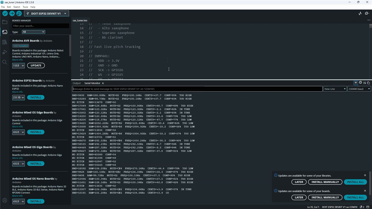
There is another useful debugging feature hidden behind all the glowing glass. The program continuously writes diagnostic information to the serial port at 230400 baud. That output includes RMS level, detected frequency, note name, distance from the target pitch in cents and pitch-detection confidence.
"You will have the volume, the frequency that it detects... if it's too high or too low, and that's a constant output. So you can also use that one instead of the light."
That serial stream is particularly useful while building or modifying the tuner. If the LEDs do not appear to behave as expected, it gives the maker a way to separate audio-detection problems from display problems. It also makes the project useful without the complete glass display, since the ESP32 and microphone can still operate as a serial-output pitch detector.
Parts for the Build
The supplied BOM combines readily sourced components with a few modules and mechanical items that Mark already had or obtained separately. The principal electronics are:
- ESP32 DOIT DevKit V1
- INMP441 I2S MEMS microphone module
- WS2812 addressable RGB LED strip
- Vishay 300Ω metal-film resistor
- TDK 100 nF, 50 V X7R radial capacitor
- Wurth Elektronik 22 µF, 10 V aluminium electrolytic capacitor
- Wurth Elektronik 100 µF, 10 V aluminium electrolytic capacitor
- Harwin 15-position sockets, quantity two
- Multicomp Pro 3-position sockets, quantity two
- TE Connectivity AMP 2-position and 3-position headers
- Prototyping board, wire and connectors
The resistor is not simply recorded as "300 ohm" in the catalogue. Farnell identifies it as Vishay MBA02040C3000FRP00, a 300Ω, 400 mW, ±1% metal-film through-hole resistor rated to 200 V. Similarly, the 100 nF component is TDK's FG18X7R1H104KNT00, a radial X7R MLCC with ±10% capacitance tolerance and a 50 V DC rating. These details are useful if you need to substitute parts or trying to reproduce the build from components already in the workshop.
More Than a Big Green Light
The finished tuner is perhaps deliberately excessive, but underneath the illuminated glass is a useful example of embedded audio processing. An I2S microphone provides digital audio directly to the ESP32, NSDF processing extracts pitch, a little filtering keeps the output responsive without making it too erratic, and an addressable LED strip turns the result into something that can be seen while actually playing an instrument.
It also fits neatly alongside Mark's other experiments with large-format audio displays. His element14 Presents biography highlights previous open-source projects including an acrylic-tile audio spectrum analyser, a 64-channel spectrum analyser and a twin audio visualiser. That makes his closing idea for this project perhaps unsurprising.
"Imagine I had 50 of those glass building blocks. What do you think I should do with them? The only thing I can think of is build a giant analyzer."
With enough blocks, individual illuminated cells could form the basis of a genuinely enormous spectrum or audio visualiser. The tuner has already dealt with several of the useful ingredients: capturing digital audio, processing it in real time, driving addressable LEDs and diffusing their light into large illuminated areas.
For now, though, the three-block version has a simpler job. Play flat and it glows red. Get the note within ten cents and the tower turns green. Go sharp and it switches to orange. No squinting at a phone screen, no tiny meter hidden behind a saxophone, and just enough giant-flux-capacitor styling to make tuning practice considerably harder to ignore.
Supporting links:
Bill of Materials
| Product Name | Manufacturer | Quantity | Buy Kit |
|---|---|---|---|
| Resistor 300ohm | Vishay | 1 | Buy Now |
| Capacitor 100nf /50v | TDK | 1 | Buy Now |
| Electrolyt Cap 22uf 10V | Wurth Elektronic | 1 | Buy Now |
| Electrolyt cap 100uf / 10V | Wurth Elektronic | 1 | Buy Now |
| socket 15p | Harwin | 2 | Buy Now |
| socket 3p | Multicomp Pro | 2 | Buy Now |
| header 2p | TE CONNECTIVITY - AMP | 1 | Buy Now |
| header 3p | TE CONNECTIVITY - AMP | 3 | Buy Now |
Additional Parts
| Product Name | Manufacturer | Quantity |
|---|---|---|
| ESP32 DEVKIT V1 | ||
| Pixelled Strip WS2812 | ||
| Wires | ||
| MEMS Mic INMP441 | ||
| Breadboard |

