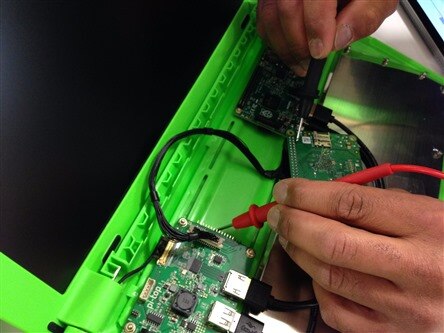
Felix is working on a Pi-Top for an upcoming episode. One of the breakout boards has an unlabeled GPIO so he was showing me the process of how he identifies and labels the pins.
(I am still learning, so I apologize if I get any of the terms wrong.)
There are two boards connected within the Pi-Top. One has a different number of pins than the other and as it turns out, has an unpredictable pattern for pin matching. Felix uses a multimeter set to resistance to discovery which pins have continuity.
This multimeter happens to have a setting that can sound an alarm when there is continuity(meaning there is a connection), so that makes this task much easier.
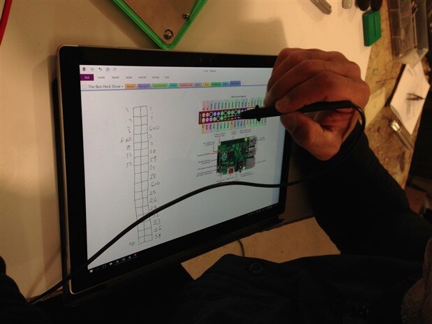
Felix has a labeled layout for the GPIO for the board on the right, so he is using that to label the board on the left.
First Felix finds the pin on the left board he is trying to identify and places the red test lead on it. Then he takes the black test lead and scrapes it along the pins on the other board until the multimeter beeps in alarm. Once he identifies which pins match, he can use the known pinout of the right board to label the board on the left.
Here, Felix has the known pinout for the right board on the right side of his tablet screen. On the left side of his tablet, he has drawn a layout of the GPIO of the other board where he can label which known pin it is connected to. The upper pin closest to Felix on the unknown board is connected to pin 40 on the other board with the known layout. Where the pin below it is connected to pin 38 of the known board, and so on.
I hope that helps out any other newbies like me. I know I learned something new today!
Hack on!
~Karen


Top Comments
-

DAB
-
Cancel
-
Vote Up
+2
Vote Down
-
-
Sign in to reply
-
More
-
Cancel
Comment-

DAB
-
Cancel
-
Vote Up
+2
Vote Down
-
-
Sign in to reply
-
More
-
Cancel
Children