Hello all! Hope I'm posting in the right place.
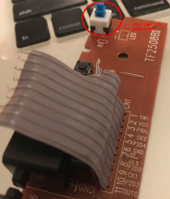
I'm currently attempting to bypass the power switch to an NES-on-a-chip style console so that plugging in a power source will automatically turn it on. Originally, the switch was located on it's own board (with some other things like controller ports) and attached back to the main brains of the unit with a ribbon cable. I've attached a picture of this (they were kind enough to provide a pin-out!)
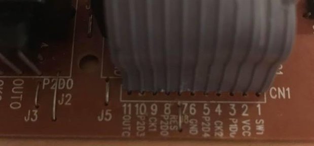
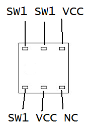
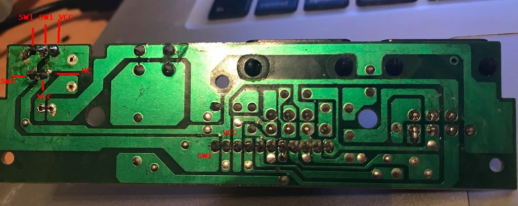
The switch in question is a 6-pin momentary switch, the exact same one as seen here and here. If you look at the second picture I've attached, you'll see how this thing is wired to the board. It appears the 5v line from the unit's 7805 is attached to the SW1 pin and not VCC (of the main board) I assumed that to bypass the switch (as I removed the entire board it was located on), I could merely bridge the VCC and SW1 pins on the main board. This did not work.
If my understanding of this is correct, this type of six pin switch is known as DPDT. I'm not entirely sure what the benefit or purpose is of using this kind of switch in this application would be. Following the video I linked previously, I used my continuity checker to see if the pins were the same as demonstrated. For whatever reason, every single pin of the switch returns continuity with each other, regardless of the state of the switch. Further compounding things is the fact that SW1 and VCC also appear to returning as having continuity with one another---which leads me to think my theory of simply bridging these lines should have worked! If you look at the picture I have attached, you can see how this switch is wired to those lines. Am I missing something really obvious, or is there more to this? Thank you all so much for your help and suggestions!
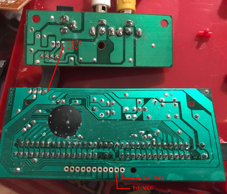
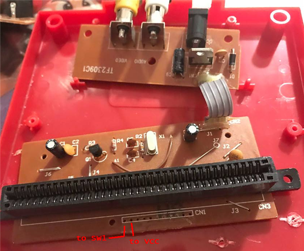
EDIT: I attached a picture of the actual board that I removed (which contains the switch circuitry in question), for reference and context, hope that helps  if needed, I can post the main board it attaches to as well, but this is the meat of it. There's a set of pads corresponding to these pins, the SW1 pad on the main board connects to the 7805 like I mentioned, as well as obviously the SW1 line on the board pictured here.
 |