element14 Community
element14 Community
    Register Log In
  • Site
  • Search
  • Log In Register
  • About Us
  • Community Hub
    Community Hub
    • What's New on element14
    • Feedback and Support
    • Benefits of Membership
    • Personal Blogs
    • Members Area
    • Achievement Levels
  • Learn
    Learn
    • Ask an Expert
    • eBooks
    • element14 presents
    • Learning Center
    • Tech Spotlight
    • STEM Academy
    • Webinars, Training and Events
    • Learning Groups
  • Technologies
    Technologies
    • 3D Printing
    • FPGA
    • Industrial Automation
    • Internet of Things
    • Power & Energy
    • Sensors
    • Technology Groups
  • Challenges & Projects
    Challenges & Projects
    • Design Challenges
    • element14 presents Projects
    • Project14
    • Arduino Projects
    • Raspberry Pi Projects
    • Project Groups
  • Products
    Products
    • Arduino
    • Avnet Boards Community
    • Dev Tools
    • Manufacturers
    • Multicomp Pro
    • Product Groups
    • Raspberry Pi
    • RoadTests & Reviews
  • Store
    Store
    • Visit Your Store
    • Choose another store...
      • Europe
      •  Austria (German)
      •  Belgium (Dutch, French)
      •  Bulgaria (Bulgarian)
      •  Czech Republic (Czech)
      •  Denmark (Danish)
      •  Estonia (Estonian)
      •  Finland (Finnish)
      •  France (French)
      •  Germany (German)
      •  Hungary (Hungarian)
      •  Ireland
      •  Israel
      •  Italy (Italian)
      •  Latvia (Latvian)
      •  
      •  Lithuania (Lithuanian)
      •  Netherlands (Dutch)
      •  Norway (Norwegian)
      •  Poland (Polish)
      •  Portugal (Portuguese)
      •  Romania (Romanian)
      •  Russia (Russian)
      •  Slovakia (Slovak)
      •  Slovenia (Slovenian)
      •  Spain (Spanish)
      •  Sweden (Swedish)
      •  Switzerland(German, French)
      •  Turkey (Turkish)
      •  United Kingdom
      • Asia Pacific
      •  Australia
      •  China
      •  Hong Kong
      •  India
      •  Korea (Korean)
      •  Malaysia
      •  New Zealand
      •  Philippines
      •  Singapore
      •  Taiwan
      •  Thailand (Thai)
      • Americas
      •  Brazil (Portuguese)
      •  Canada
      •  Mexico (Spanish)
      •  United States
      Can't find the country/region you're looking for? Visit our export site or find a local distributor.
  • Translate
  • Profile
  • Settings
element14 presents
  • Challenges & Projects
  • More
element14 presents
element14 presents Forum My Retropie Portable Build
  • Blog
  • Forum
  • Documents
  • Polls
  • Files
  • Members
  • Mentions
  • Sub-Groups
  • Tags
  • More
  • Cancel
  • New
Join element14 presents to participate - click to join for free!
Actions
  • Share
  • More
  • Cancel
Forum Thread Details
  • Replies 12 replies
  • Subscribers 109 subscribers
  • Views 2307 views
  • Users 0 members are here
  • portable pi
  • 7 inch touchscreen display
  • li-po charging
  • retropie
Related

My Retropie Portable Build

celcius1
celcius1 over 6 years ago

Hey Guys,


I've decided to discuss my Retropie Handheld build, I would love feedback if it is constructive, now I had a 7" RPi touchscreen lying around, and decided to build it into a Retropie portable, now power requirements, had to be considered, now Powerboost chargers from adafruit wont cut it with the current feed needed for the RPi 3B+, so for the Power source, I'm using 4 LiPo cells, with a capacity of 4000mAh, wired as two packs, so i have two packs with an output voltage of 7.2v and then in parallel so I have a battery capacity of 8000mAh.  I also cant use Adafruit stuff as there are no local stockists of the modules here in Adelaide.


But with the charging circuit I've modified one I found for charging 4 cells that uses an ATMega328P, the changes I'm making is for charging 2 cells even though I'm using 4, I am assuming I can treat the two packs of two cells as two cells to the circuit.  The other change is to add a means to switch from battery power to PSU when it is plugged in for charging. and load share between the pi and battery, the power from the PSU or battery then goes into a Buck Converter, (https://www.altronics.com.au/p/z6334-dc-dc-buck-module-3-40v-input/), so I can give the Pi and screen upto 2.5A at 5v.  Also I'll be adding a means to the battery charging circuit if a low battery condition is detected, so that it can signal the RPi to shutdown if the voltage drops below a set threshold.


Now the reason for building my own charging interface is because here in Australia we don't have much in the way of standard modules, even ones with the power requirements of the RPi 3B+, plus I prefer a bigger handheld screen.


This is the reference I am using for building my own version of the charging circuit https://www.microfarad.de/li-charger/ this site is quite informative, and will help in customising this circuit for my requirements.


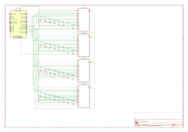
For the buttons I am going to use a basic key matrix, and take a page from the TBHS project where they did this, as its a good proven method of input.


The batteries I am using https://www.altronics.com.au/p/s4761-26650-lithium-ion-3.6V-4000mah-rechargeable-battery/

Controller I am using for charging https://www.altronics.com.au/p/z6222-sparkfun-dev-11113-pro-mini-328-5v-16mhz/

Plugpack for External power and Charging https://www.altronics.com.au/p/m8936b-powertran-12v-dc-2a-fixed-2.1mm-tip-appliance-plugpack/


I value constructive feedback of my project.


I also forgot to add, once I get the handheld working, I'm going to look at expanding it so I can plug 2600 cartridges directly into it, as I have been working on a 2600 cartridge interface. running into a few hurdles, so focusing on something a little easier image


Regards


Paul


P.S. I'm umming and rring about actually recording this on video and doing a video of project.

  • Sign in to reply
  • Cancel

Top Replies

  • celcius1
    celcius1 over 6 years ago +2
    After speaking with my battery supplier, I've decided to go with 18650 Li-Ion cells, with 3 cells per bank, giving a battery voltage of 10.8V and battery life of approx 7hrs. as when the handheld is on…
  • shabaz
    shabaz over 5 years ago in reply to celcius1 +2
    Hi Paul, There are other ways to design keyboard circuits that reduce the need for so many parts, you've got 37 parts here not including the buttons. These can be reduced to 2 parts, like two MCP23017…
  • celcius1
    celcius1 over 5 years ago +1
    It's been awhile since working on this, I've made a few changes since I originally started. Change 1 I'm using a different 7inch screen, that is driven by a HDMI and usb for power and Touch https://www…
  • celcius1
    celcius1 over 5 years ago +1
    Also with the battery component, I've done more research, and are working on integrating a battery balancing system in the charging circuit, and have decided to go with a 18v battery pack as when I did…
  • shabaz
    shabaz over 5 years ago +1
    Hi Paul, Connecting parallel/series batteries can be high-risk, you've not mentioned if the latest battery pack is self-assembled. The original one you mentioned was not (the one that was going to be 4…
  • celcius1
    celcius1 over 5 years ago in reply to shabaz +1
    Hi Shabaz, The battery packs are being professionally made of 4 cells each behind each hand hold, total of 8 cells, at 14.8v, they will have to sets of wires on it one for pack connection and the other…
  • celcius1
    celcius1 over 5 years ago +1
    So I have got most the schematic drawn up for the button matrix, I still have a number of items to put on the schematic most importantly a logic level shifter as the shift registers are logic level 5v…
  • celcius1
    celcius1 over 5 years ago in reply to shabaz +1
    Hi Shabaz, Thanks for the suggestion I'll make a change to my schematic, I'm reading up on the chip now, trying to find the SPI commands, as I've started coding the source file to read the button states…
  • shabaz
    shabaz over 5 years ago in reply to celcius1 +1
    Hi Paul, I've not coded using the library you're using or for this device, so cannot help much here. It may be instead worthwhile using a GPIO library (such as wiringPi or some other one, I don't know…
  • celcius1
    celcius1 over 5 years ago in reply to shabaz +1
    Hi Shabaz, I Redesigned my Key Matrix, and re wrote my code. I'm using 74HC165 now, which are proper input shift registers or PISO registers, don't need to use protection diodes on the pins, and the IC…
Parents
  • celcius1
    celcius1 over 5 years ago

    So I have got most the schematic drawn up for the button matrix, I still have a number of items to put on the schematic most importantly a logic level shifter as the shift registers are logic level 5v devices along with the inverter.


    But a description of the circuit function.


    The matrix is polled approx every 1 to 5 milliseconds, With the SPI bus set to run on a 6.25MHz clock,  The SPI input is expecting a 32bit binary value, these 32 bits represent the buttons.


    Once a read starts chip enable 0 is activated turning on the shift registers, firstly a single bit is loaded into the shift register, then Chip enable 1 is activated, to connect the register clock to the SPI clock to start clocking through the buttons.


    As the clock cycles through the button matrix, the inverter facilitates the output of the data on the shift registers output lines on the falling edge of the clock, as the clock cycles the data through the registers if a button is pressed it sends a logic 1 to the SPI bus, to indicate a button that has been pressed, once a cycle is complete, this 32 bit value can be analysed to see which buttons have been pressed


    once this is in memory it can then be analysed to see which buttons have been pressed by means of a lookup table.


    The reason for a 6.25MHz clock is the speed of the chips being used, the shift registers cant operate much faster, but in saying that I could easily use a slower clock as at 6.25MHz clock I can do a full matrix read in approx 6 to 7 microseconds


    I would like some feedback to know if this design is sound, and then I'll have to spend time working out the code on how to read the matrix, and how to assign the lookup table

    image

    • Cancel
    • Vote Up +1 Vote Down
    • Sign in to reply
    • Cancel
  • shabaz
    shabaz over 5 years ago in reply to celcius1

    Hi Paul,

    There are other ways to design keyboard circuits that reduce the need for so many parts, you've got 37 parts here not including the buttons. These can be reduced to 2 parts, like two MCP23017 chips, and they are available in through-hole and surface-mount versions.


    I've not tried it for a games system, so you'd have to experiment to rule it in or out, but I think if you software-enable pull-ups and configure the MCP chips to be all inputs, then you can configure it to signal via interrupt when any switch input changes. No need to do so much scanning basically.


    Anyway, regardless of what you go with, it is best to prototype a bit of this (e.g. on a breadboard) before creating a PCB, i.e. by PCB creation stage there should be near-100% confidence that worst-case nothing other than one or two 'bodge' wires may be necessary to get the prototype working. Not all of it needs to be prototyped, but at least some buttons and a few of the chips.

    Each chip should have a 100nF capacitor across the supply rails, as close to the chip as possible, this may also be indicated in the datasheets for the ICs. Also, the Pi is a 3.3V logic device, it's a bit dangerous to run the circuit shown above from 5V. Although it could be level-converted, it is better to power off the 3.3V rail provided you don't draw too much current (which a keyboard driver circuit shouldn't anyway). Also, for U5, 74LS366, the 74HC would be used instead (LS isn't suitable for 3.3V operation).

    • Cancel
    • Vote Up +2 Vote Down
    • Sign in to reply
    • Cancel
  • celcius1
    celcius1 over 5 years ago in reply to shabaz

    Hi Shabaz,


    Thanks for the suggestion I'll make a change to my schematic, I'm reading up on the chip now, trying to find the SPI commands, as I've started coding the source file to read the button states, but you know of anyone with programming experience that might be able to help me ensure my code is correct, and enable it is a pre-configured key mapping?


    Attached is the code I have worked out so far, still needs work be aware its currently written for my current schematic


    I read up on the chip, It’s a lot more difficult to program SPI commands have way too much overhead, but another option I have is it use a 74HC166 which is a proper input chip, but the reasoning behind my design is the ability to source parts, not easy to do here in Australia


    Regards

    Paul

    #include <bcm2835.h>
    #include <stdio.h>
    
    int main(int argc, char **argv)
    {
        
        if (!bcm2835_init())
            return 1;
            
        const int start_poll = 0x01;                                  // Initial Byte sent to Shift Register to do button read by setting Qa in the shift register to logic high
        char button_state[]= {0x00, 0x00, 0x00, 0x00];                  // 32 bit 4 byte array to store the button states
        
            
        bcm2835_spi_begin();
        bcm2835_spi_setBitOrder(BCM2835_SPI_BIT_ORDER_MSBFIRST);      // Set Byte Transfer Read Order
        bcm2835_spi_setDataMode(BCM2835_SPI_MODE0);                   // Default Transfer Mode
        bcm2835_spi_setClockDivider(BCM2835_SPI_CLOCK_DIVIDER_64);    // Clock set to RPi 2 to 3.90625MHz or on RPi 3 to 6.25 MHz
        
            
        bcm2835_spi_chipSelect(BCM2835_SPI_CS0);                      // Enable Shift Registers Only
        bcm2835_spi_setChipSelectPolarity(BCM2835_SPI_CS0, LOW);      // Set Shift Register Enable Polarity to Active Low
        bcm2835_spi_transfer(start_poll);                              // Set First Shift Register Qa Output to Logic High
        bcm2835_spi_chipSelect(BCM2835_SPI_CS1);                      // Select All devices and Register Clock 
        bcm2835_spi_setChipSelectPolarity(BCM2835_SPI_CS1, LOW);      // Set Chip Enable Polarity to Active Low
        bcm2835_spi_transfern(button_state, sizeof(button_state));    // Read the button Status
        
        
        bcm2835_spi_end();
        return 0;
    }

    • Cancel
    • Vote Up +1 Vote Down
    • Sign in to reply
    • Cancel
  • shabaz
    shabaz over 5 years ago in reply to celcius1

    Hi Paul,


    I've not coded using the library you're using or for this device, so cannot help much here.

    It may be instead worthwhile using a GPIO library (such as wiringPi or some other one, I don't know what's recommended these days for Pi), otherwise you'll need to modify and retest bits of code if you change Pi variant.

    Another suggestion is using a logic analyzer (some are low-cost, search for 'salae logic' for instance) when coding for hardware like this.

    • Cancel
    • Vote Up +1 Vote Down
    • Sign in to reply
    • Cancel
Reply
  • shabaz
    shabaz over 5 years ago in reply to celcius1

    Hi Paul,


    I've not coded using the library you're using or for this device, so cannot help much here.

    It may be instead worthwhile using a GPIO library (such as wiringPi or some other one, I don't know what's recommended these days for Pi), otherwise you'll need to modify and retest bits of code if you change Pi variant.

    Another suggestion is using a logic analyzer (some are low-cost, search for 'salae logic' for instance) when coding for hardware like this.

    • Cancel
    • Vote Up +1 Vote Down
    • Sign in to reply
    • Cancel
Children
  • celcius1
    celcius1 over 5 years ago in reply to shabaz

    Hi Shabaz,


    I Redesigned my Key Matrix, and re wrote my code.  I'm using 74HC165 now, which are proper input shift registers or PISO registers, don't need to use protection diodes on the pins, and the IC's are 3.3v logic level.


    image

    Now below is my code to communicate with the shift registers using wiringPi, but what concerns me it does not tell me if the Chip Select is in Active Low or Active High mode, when it accesses the SPI bus.  I can always test this when my chips arrive had to buy a tube of 50 of them from RS Components and got some breakout boards so I can easily breadboard the IC's as they are an SOIC package.  But if WiringPi cant use the SPI bus correctly, cause of the simple nature of the shift registers I could manually shift the data in but this is alot of coding work to do this, and I prefer not to go down this path.


    #include <wiringPi.h>
    #include <wiringPiSPI.h>
    #include <stdio.h>
    
    int main(void)
    {
        
        char button_state[]= {0x00, 0x00, 0x00, 0x00];                  // 32 bit 4 byte array to store the button states
        int i;
                
        wiringPiSetup();                                            // Initialise Wiring Pi
        wiringPiSPISetup (0, 3000000);                                // Initialise Wiring Pi SPI interface With 3MHz clock
        pinMode (26, OUTPUT);                                        // Setup Parallel Load pin as Output
        
        digitalWrite (26, LOW);                                        // Pull Parallel Load Pin to Logic Low to load data
        delayMicroseconds (1);                                        // Wait one Microsecond for data to stabilise
        digitalWrite (26, HIGH);                                    // Pull Parallel Load Pin to Logic High to load data into serial register
        
        wiringPiSPIDataRW (0, button_state, sizeof(button_state));    // Read data from Shift Registers with SPI of a 32bit value
            
        for (i = 0; i < 3; i++)
        {
            printf(button_state[i], "\n");
        }
    }


    for the moment the code only just prints out the contents of the array, but eventually I need to find out how to map this data to a device tree overlay that references specific assigned keyboard buttons.


    Regards

    Paul

    • Cancel
    • Vote Up +1 Vote Down
    • Sign in to reply
    • Cancel
  • shabaz
    shabaz over 5 years ago in reply to celcius1

    Hi Paul,

    Each input that is connected to a switch needs a resistor (in your case a pull-down resistor, such as a 10 k resistor) otherwise each input is floating until a switch is pressed.

    Is the requirement to have the Chip select be normally low, and then to go high when accessing the chips? If so, you could wire it to any other pin on the Pi and manually set it. Or, just permanently wire it high if that works for your circuit (I have not checked). Also, 100nF capacitors are needed.

    Use what you're most comfortable with, I just personally feel using a library like wiringPi is far reduced coding (and more reliable) compared to trying to access BCM.. registers manually.

    Also, no matter how confident you are, I'd suggest just buying a few of the ICs and trying it out, rather than buying a tube of 50 if there's a risk your design may change and use a different device. ebay Australia (I would not normally suggest ebay, but if you're struggling to obtain fewer quantities from a distributor) has them in single quantity: https://www.ebay.com.au/itm/74HC165-8-bit-parallel-in-out-Shift-Register-IC/254545886099?epid=1963682493&hash=item3b441d…

    • Cancel
    • Vote Up +1 Vote Down
    • Sign in to reply
    • Cancel
  • celcius1
    celcius1 over 5 years ago in reply to shabaz

    The Clock Enable is Active Low, and when it is pulled low starts clocking the data out serially on the rising edge of pulse.


    And I have investigated manually clocking out the data using the GPIO and not the SPI protocol, but it adds a lot more to the code, which I can do, but SPI can read the data in approx 6 microseconds whereas if I code it manually and ensure the slowest delay time of one microsecond per data read I’m looking at approx 40 microseconds to read the data but in thinking that thru, it’s still a short space of time, but I still need to poll the registers.


    Also if I increase the component count again, I can use shotky diodes to tie, all the input lines to a single GPIO pin looking for a button push, and essentially give me an interrupt. But prevent the other lines from being affected.  As much as I could interface a standard row and column approach, I want to keep the amount of GPIO I use to a minimum if I need more in future if I use the same 32 button input hardware.


    ill do a bit more work, and clean up the schematic and I’ll also write the code that handles the data scan manually using wiringpi


    i Didn’t mind buying the tube and the IC is a standard one for adding in more inputs, so don’t worry I’ll end up using them. And the tube only cost me $25


    its late here I’ll do it during the day, bed time for me


    Regards

    Paul

    • Cancel
    • Vote Up +1 Vote Down
    • Sign in to reply
    • Cancel
element14 Community

element14 is the first online community specifically for engineers. Connect with your peers and get expert answers to your questions.

  • Members
  • Learn
  • Technologies
  • Challenges & Projects
  • Products
  • Store
  • About Us
  • Feedback & Support
  • FAQs
  • Terms of Use
  • Privacy Policy
  • Legal and Copyright Notices
  • Sitemap
  • Cookies

An Avnet Company © 2025 Premier Farnell Limited. All Rights Reserved.

Premier Farnell Ltd, registered in England and Wales (no 00876412), registered office: Farnell House, Forge Lane, Leeds LS12 2NE.

ICP 备案号 10220084.

Follow element14

  • X
  • Facebook
  • linkedin
  • YouTube