element14 Community
element14 Community
    Register Log In
  • Site
  • Search
  • Log In Register
  • About Us
  • Community Hub
    Community Hub
    • What's New on element14
    • Feedback and Support
    • Benefits of Membership
    • Personal Blogs
    • Members Area
    • Achievement Levels
  • Learn
    Learn
    • Ask an Expert
    • eBooks
    • element14 presents
    • Learning Center
    • Tech Spotlight
    • STEM Academy
    • Webinars, Training and Events
    • Learning Groups
  • Technologies
    Technologies
    • 3D Printing
    • FPGA
    • Industrial Automation
    • Internet of Things
    • Power & Energy
    • Sensors
    • Technology Groups
  • Challenges & Projects
    Challenges & Projects
    • Design Challenges
    • element14 presents Projects
    • Project14
    • Arduino Projects
    • Raspberry Pi Projects
    • Project Groups
  • Products
    Products
    • Arduino
    • Avnet Boards Community
    • Dev Tools
    • Manufacturers
    • Multicomp Pro
    • Product Groups
    • Raspberry Pi
    • RoadTests & Reviews
  • Store
    Store
    • Visit Your Store
    • Choose another store...
      • Europe
      •  Austria (German)
      •  Belgium (Dutch, French)
      •  Bulgaria (Bulgarian)
      •  Czech Republic (Czech)
      •  Denmark (Danish)
      •  Estonia (Estonian)
      •  Finland (Finnish)
      •  France (French)
      •  Germany (German)
      •  Hungary (Hungarian)
      •  Ireland
      •  Israel
      •  Italy (Italian)
      •  Latvia (Latvian)
      •  
      •  Lithuania (Lithuanian)
      •  Netherlands (Dutch)
      •  Norway (Norwegian)
      •  Poland (Polish)
      •  Portugal (Portuguese)
      •  Romania (Romanian)
      •  Russia (Russian)
      •  Slovakia (Slovak)
      •  Slovenia (Slovenian)
      •  Spain (Spanish)
      •  Sweden (Swedish)
      •  Switzerland(German, French)
      •  Turkey (Turkish)
      •  United Kingdom
      • Asia Pacific
      •  Australia
      •  China
      •  Hong Kong
      •  India
      •  Korea (Korean)
      •  Malaysia
      •  New Zealand
      •  Philippines
      •  Singapore
      •  Taiwan
      •  Thailand (Thai)
      • Americas
      •  Brazil (Portuguese)
      •  Canada
      •  Mexico (Spanish)
      •  United States
      Can't find the country/region you're looking for? Visit our export site or find a local distributor.
  • Translate
  • Profile
  • Settings
555 Timer Madness
  • Challenges & Projects
  • Project14
  • 555 Timer Madness
  • More
  • Cancel
555 Timer Madness
Blog Capacitance Meter Using 555 and Decade counter
  • Blog
  • Forum
  • Documents
  • Events
  • Leaderboard
  • Polls
  • Files
  • Members
  • Mentions
  • Sub-Groups
  • Tags
  • More
  • Cancel
  • New
Join 555 Timer Madness to participate - click to join for free!
  • Share
  • More
  • Cancel
Group Actions
  • Group RSS
  • More
  • Cancel
Engagement
  • Author Author: vinayyn
  • Date Created: 8 Oct 2022 8:40 PM Date Created
  • Views 12176 views
  • Likes 11 likes
  • Comments 3 comments
  • ne555
  • 555timermadnessch
  • 555 timers
  • 555 Timer Madness
Related
Recommended

Capacitance Meter Using 555 and Decade counter

vinayyn
vinayyn
8 Oct 2022

The 555 timers were the first ever Integrated Circuits I have used in my life and learned a lot while experimenting with them by blinking LED, creating sound alarms, and timer-based Outdoor lights. After this, I used 555 timers to generate PWM to create an inverter, and the list keeps on increasing till today.

image

While working with the 555 timers Astable Multivibrators, I always wanted to learn to measure the capacitance of unknown capacitors. This is because while storing Ceramic capacitors in my storage unit I mistakenly put the capacitors and not be able to recognize the capacitor values due to Code Was erased. To find capacitance I had to depend on measuring the capacitor using LCR Meter in my college lab, during my college days capacitance measuring options were not in the multimeters so I built my capacitance measuring meter using an astable multivibrator and decade counter.

Here I have used a 555 timer IC along with a 74LS90 Decade counter to measure the capacitance using DC Ammeter.

555 Timer is used as a square wave generator in this circuit. During the High (1) square wave cycle, the capacitor (Cx) charges up to approximately 3.5 volts. During the Low(0) Cycle, the capacitor starts discharging.

image

The 555 Timer clock frequency(f) will determine the discharge current through the ammeter. since Equation 1,

Q = C x V

Then,

fQ = fC x V          ......(Equation 1)

The Quantity fQ is the number of coulombs of charge stored per second, and it is equal to the average current Flowing Through the capacitor(Cx)

fQ = dQ/Ddt = i

or,

i = f C x V           ........(Equation 2)

for example, assume an ammeter-sensitive scale is 100 microammeter, the clock frequency required to give a 0.1uf  full-scale reading is found by rearranging equation 2,

f = i/ C x V

= 100uA/0.1uF x 3.4V

f = 294Hz

Working Principle

The NE555 is used as an astable multivibrator in this circuit, it generates the square wave at the frequency of 48KHz with a 66% duty cycle rate. i have chosen R1,R2 = 1K ohm and c = 0.01uF.

image

To find the frequency f = 1.44/(R1+2R2) X C

                                     = 1.44(1K+2X1k) X 0.01u

                                     = 48 KHz (Theoretical Value)

48KHz square wave signal is connected to the Decade counter Clock input, the 74LS90 Is activated to count function by enabling R0(1), R9(1) to Logic 0

image

A Rotary switch is used in this circuit to select the measuring scale range, This circuit can able to measure the Capacitor Value from 1nf - 10uF.

Circuit Diagram
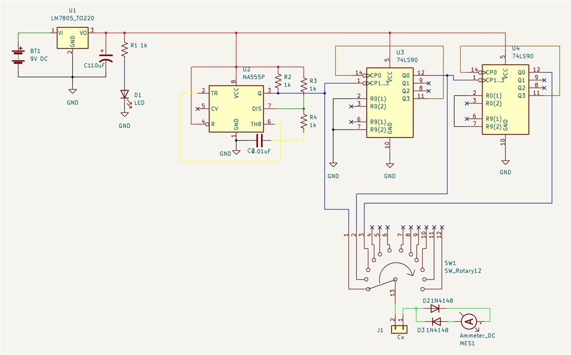
image

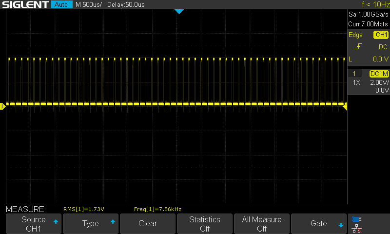
Output Waveform Of 555 Timer The theoretical Output frequency is 48KHz and the Practical Output Of the Circuit was 39kHz

image

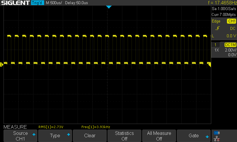
Output Of First Decade counter on the 12th pin of the IC  (Output of First counter is then Fed to 2nd counter)
image

Output Of Second Decade counter on the 12th pin of the IC
image

Output Result Video

You don't have permission to edit metadata of this video.
Edit media
x
image
Upload Preview
image

Circuit Diagram PDF

  • Sign in to reply
  • vinayyn
    vinayyn over 2 years ago in reply to dougw

    thank you

    • Cancel
    • Vote Up 0 Vote Down
    • Sign in to reply
    • More
    • Cancel
  • dougw
    dougw over 2 years ago

    Nicely documented.

    • Cancel
    • Vote Up 0 Vote Down
    • Sign in to reply
    • More
    • Cancel
  • Jan Cumps
    Jan Cumps over 2 years ago

    Great!

    • Cancel
    • Vote Up 0 Vote Down
    • Sign in to reply
    • More
    • Cancel
element14 Community

element14 is the first online community specifically for engineers. Connect with your peers and get expert answers to your questions.

  • Members
  • Learn
  • Technologies
  • Challenges & Projects
  • Products
  • Store
  • About Us
  • Feedback & Support
  • FAQs
  • Terms of Use
  • Privacy Policy
  • Legal and Copyright Notices
  • Sitemap
  • Cookies

An Avnet Company © 2025 Premier Farnell Limited. All Rights Reserved.

Premier Farnell Ltd, registered in England and Wales (no 00876412), registered office: Farnell House, Forge Lane, Leeds LS12 2NE.

ICP 备案号 10220084.

Follow element14

  • X
  • Facebook
  • linkedin
  • YouTube