Commit to a hobby project was not as simple as I thought. My plan to Madness 555 was very simple: crafting a fun idea, using an abnormal way to implement it, sticking with the plan toward the finish line. Today is the deadline for the contest of Madness 555. I think I made it. Here is my story.
Phase 1: Crafting a fun idea
I like LED projects. Dynamic and colorful movement from a LED project can cheer me up in my dark basement lab. There have been so many 555 projects over the past 50 years. I don’t think I knew all of them. So learning by doing would be a good excuse to join the game. Here is my idea formula:
LED+GAME+555=my project.
Ring counter is a good fit for my formula. I need a reasonable size ring flashed by LEDs. NE 555 can do counting and triggering. A chasing game can be made from it. There are two colors of LEDs in the ring. Only one LED has different color as the rest of the LEDs. I use blue for the unicorn LED and the rest LEDs are yellow. 555 timer controls one LED being ON one time. There is a push button in the circuit. If I push the button at the same moment that the blue LED is ON, I win. There is a bigger blue LED at the center of the ring. If I win, the reward is that the center LED will be ON at the same time to let me know I am in a sync status with the ring’s movement.
Phase 2: Using a way not very common
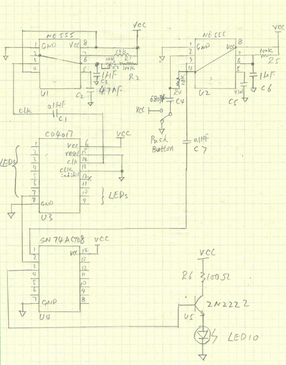
My circuit for the project is a traditional way. One timer for counter 10 LEDS in serial way, another timer for one shot trigger from the push button. One shot trigger from NE555 is a funny piece. I tried to manipulate C4/R4 parameters to change the length of trigger, but the length of the trigger was no difference, so the flash moment of the bigger blue LED was not improved. I might need another NE555 for the length of the trigger ON time. I assume my readers are familiar with NE555+CD4017= counter, NE555 one shot timer working theory. I added a NPN gate to booster the current from VCC source since SN74AC708 from TI SOIC package can only supply less than 24 mA current. The bigger blue LED needs around 30~40mA to get proper color. I did not add any decoupling capacitors at each IC’s VCC pins to save the work from the wiring. Here is my schematic for the project:

I need to add some challenges into the project. I choose to use copper wires to connect the IC chips and implement the circuits without any breadboard or PCB board. It is my first time to soldering circuits with so many jumping wires. It was not a usual way for me to build a circuit but fun.
Here is my breadboard version of the project:
Here is my copper wire version of the project:
Phase 3: Finishing the project and warping up the report
Here is my video record of the final project. I am doing this project for celebrating 555 IC chip and also trying to cheer up the fun activities within Element14 community.
