We all like LEDs, simple LEDs, or LED displays, such as those 7-segment, 4-digit displays. I use them more with Arduino platforms, they are useful and also more visible than other types of displays. In order to be able to use a 4-digit, 7-segment display together with an Arduino platform, we need to take care of a few things: according to the ATmega328P data sheet, the total current from all I / O pins should not exceed 200mA (DC power pins VCC-GND) or, we look at the DC current per pin I / O which is a maximum of 40mA (it doesn't hurt to go on an average value of 20 mA); the brightness of the display, for most displays, each segment is rated up to 20 mA (we usually go 10 mA, especially if we use a red color display, which is more visible), so if all 7 segments plus DP are lit, the power consumption (at 10mA) would be 80mA, or it could reach up to 160mA if we go to the highest values. Considering all this, it would not be very appropriate to use a 7-segment display with 4 digits together with an Arduino platform, so I chose another solution, maybe more reliable, plus the fact that the number of connections is lower.
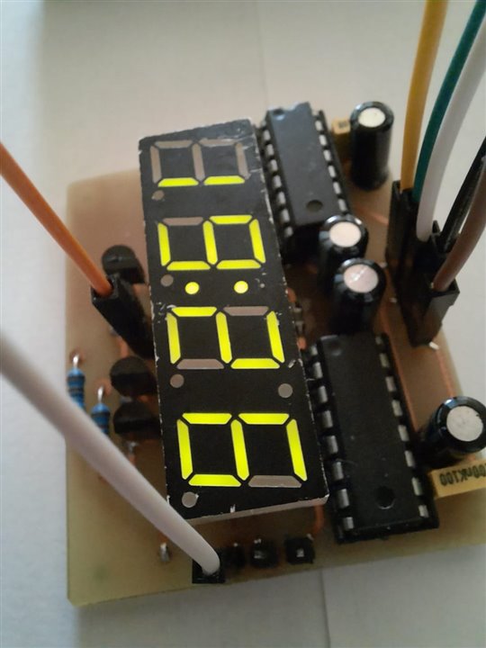
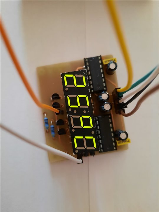
I used a 74HC595 serial shift register, which is only able to output a maximum of 70mA, but if we add some bipolar transistors we manage to do a pretty good job. So, below you can see some pictures with a homemade PCB and a 7-segment display with 4 digits common anode type, in green color; I don't have the best methods for making PCBs, but I think it turned out pretty well. This display shows the time, temperature and humidity in the room, I used an RTC and DHT11, plus an Arduino board. I couldn't figure out what the display model is, but with a DMM and an internet search I discovered the functionality of the pins. There are also 1k resistors in the circuit, 2N3906 PNP transistors, some male pins and some capacitors near the 74HC595 power pins.
This display has several pins, in addition to the digital + DP pins and segments, we also have a single LED in the upper right corner, and two LEDs in the center. The PCB is designed by me in KiCad, homemade, in two layers, with hand-mounted vias, and 0.8mm thick tracks. I used THD components because I have them at hand, the PCB would be smaller if I used more SMDs.
Other projects will follow.
You can find the circuit below.
.
/resized-image/__size/1280x720/__key/communityserver-blogs-components-weblogfiles/00-00-00-03-68/554.jpeg /resized-image/__size/1280x720/__key/communityserver-blogs-components-weblogfiles/00-00-00-03-68/665.jpeg/resized-image/__size/1280x720/__key/communityserver-blogs-components-weblogfiles/00-00-00-03-68/364.jpeg
 /resized-image/__size/1280x720/__key/communityserver-blogs-components-weblogfiles/00-00-00-03-68/147.jpeg/cfs-file/__key/communityserver-blogs-components-weblogfiles/00-00-00-03-68/777.mp4/resized-image/__size/1280x720/__key/communityserver-blogs-components-weblogfiles/00-00-00-03-68/schema.png

Top Comments