


I did this project back in 2012 as my minor project. This project was inspired by the need for a method to neutralize threats without the direct intervention of humans. That was the time, my country was hard hit by violence which motivated me to develop a simple robot vehicle that can be operated by any mobile phone. The robot is controlled via DTMF audio frequencies which enables it to have wider operational coverage even in 2G networks.
Let's inspect the basic structure of the robot.
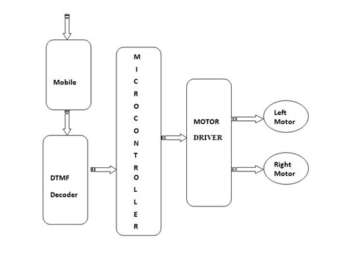
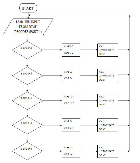
The mobile handset which is shown there is used to control the robot. We make a call to the handset which is placed inside the robot, the robot then automatically accepts the call and then we have to press each key to control the motion of the robot, which is controlled with the help of microcontroller associated with it. The robot can be reset with the help of the external reset switch. Each switch is allotted for each operation. When the key corresponding to the motion of the robot is pressed, the DTMF decoder will decode the tone generated at the receiver and sends the binary code to the microcontroller. The microcontroller is programmed in such a way that when the binary codes corresponding to the motion are detected, the microcontroller will give the corresponding binary input to the motor driver. The motor driver will interpret the signal and will give the motor appropriate voltages thereby switches it and rotates the motor in the corresponding direction.
HARDWARE REQUIREMENTS
- M8870 DTMF decoder
- Microcontroller
- L293D Motor Driver
- DC Motors
- Robot car structure kit
- Cell phone
- 5v Regulated power supply
DTMF DECODER:
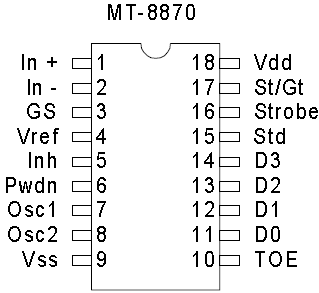
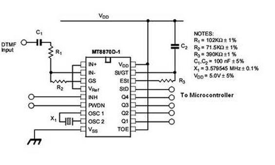
The M8870 is a full DTMF Receiver that integrates both the band split filter and decoder functions into a single 18-pin DIP or SOIC package. Manufactured using CMOS process technology, the M-8870 offers low power consumption (35 mW max) and precise data handling. Its filter section uses switched capacitor technology for both the high and low group filters and for dial tone rejection. Its decoder uses digital counting techniques to detect and decode all 16 DTMF tone pairs into a 4-bit code. External component count is minimized by the provision of an on-chip differential input amplifier, clock generator, and latched tri-state interface bus. Minimal external components required include a low-cost 3.579545 MHz color burst crystal, a timing resistor, and a timing capacitor. The M-8870-02 provides a “power-down” option which, when enabled, drops consumption to less than 0.5 mW. The M-8870-02 can also inhibit the decoding of fourth column digits.
Features of M8870:
- Complete DTMF Receiver
- Low power consumption (35mw)
- Internal gain setting amplifier
- Adjustable acquisition and release times
- Central office quality
- Power-down mode (5mw)
- Single 5 Volt power supply
- Dial tone suppression
- Inhibit mode
The DTMF technique outputs a distinct representation of 16 common alphanumeric characters (0-9, A-D, *, #) on the telephone. The lowest frequency used is 697 Hz and the highest frequency used is 1633Hz. The DTMF keypad is arranged such that each row will have its own unique tone frequency and also each column will have its own unique tone frequency. Above is a representation of the typical DTMF keypad and the associated row/column frequencies. By pressing a key, for example, 5, will generate a dual-tone consisting of 770 Hz for the low group and 1336 Hz for the high group.

MICROCONTROLLER :
The microcontroller we use here is AT89C51. The AT89C51 is a low-power, high-performance CMOS 8-bit microcomputer with 8K bytes of Flash programmable and erasable read-only memory (PEROM). The device is manufactured using Atmel’s high-density non-volatile memory technology and is compatible with the industry-standard 80C51 and 80C52 instruction set and pinout. It is a controlling unit that can be programmed as per requirements. In this project, it accepts the binary code corresponding to the detected tone is received and the binary code to drive the motors will be sent to the driver IC.
Features:
- ATMEL’s product
- Similar to 8051
- 8-bit microcontroller
- Uses EPROM or FLASH memory
- Multiple time programmable(MTP)
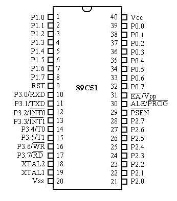
The ATMEL89C51 has a total of 40 pins that are dedicated to various functions such as I/O, RD, WR, address and interrupts. Out of 40 pins, a total of 32 pins are set aside for the four ports P0, P1, P2, and P3, where each port takes 8 pins. The rest of the pins are designated as Vcc, GND, XTAL1, XTAL, RST, EA, and PSEN. All these pins except PSEN and ALE are used by all members of the 8051 and 8031 families.
Pin Description
|
Pin Number |
Pin Name |
Description |
|
1 |
P1.0 |
0th pin of PORT P1 |
|
2 |
P1.1 |
1st pin of PORT P1 |
|
3 |
P1.2 |
2nd pin of PORT P1 |
|
4 |
P1.3 |
3rd pin of PORT P1 |
|
5 |
P1.4 |
4th pin of PORT P1 |
|
6 |
P1.5 |
5th pin of PORT P1 |
|
7 |
P1.6 |
6th pin of PORT P1 |
|
8 |
P1.7 |
7th pin of PORT P1 |
|
9 |
RST |
Reset pin of the Microcontroller |
|
10 |
(RXD) P3.0 |
0th pin of PORT P3 or Receiver pin of Microcontroller |
|
11 |
(TXD) P3.1 |
1st pin of PORT P3 or Transmitter pin of Microcontroller |
|
12 |
(INT0) P3.2 |
2nd pin of PORT P3 or External Interrupt 0 of MCU |
|
13 |
(INT1) P3.3 |
3rd pin of PORT P3 or External Interrupt 1 of MCU |
|
14 |
(T0) P3.4 |
4th pin of PORT P3 or Timer 0 interrupt of MCU |
|
15 |
(T1) P3.5 |
5th pin of PORT P3 or Timer 1 interrupt of MCU |
|
16 |
(WR) P3.6 |
6th pin of PORT P3 or Write to External data memory pin |
|
17 |
(RD) P3.7 |
7th pin of PORT P3 or Read from External data memory pin |
|
18 |
XTAL2 |
External crystal pin 2 of Microcontroller |
|
19 |
XTAL1 |
External crystal pin 1 of Microcontroller |
|
20 |
GND |
Ground pin of MCU |
|
21 |
P2.0(A8) |
0th pin of PORT P2 or High-order Address bit 8 of MCU |
|
22 |
P2.1(A9) |
1st pin of PORT P2 or High-order Address bit 9 of MCU |
|
23 |
P2.2(A10) |
2nd pin of PORT P2 or High-order Address bit 10 of MCU |
|
24 |
P2.3(A11) |
3rd pin of PORT P2 or High-order Address bit 11 of MCU |
|
25 |
P2.4(A12) |
4th pin of PORT P2 or High-order Address bit 12 of MCU |
|
26 |
P2.5(A13) |
5th pin of PORT P2 or High-order Address bit 13 of MCU |
|
27 |
P2.6(A14) |
6th pin of PORT P2 or High-order Address bit 14 of MCU |
|
28 |
P2.7(A15) |
7th pin of PORT P2 or High-order Address bit 15 of MCU |
|
29 |
PSEN |
Program store enable pin, Read external program memory |
|
30 |
ALE/PROG |
Address Latch Enable/ Program Pulse input for flashing |
|
31 |
EA/VPP |
Access Enable voltage/Program enable voltage |
|
32 |
P0.7(AD7) |
7th pin of PORT P0 or Low-order Address bit 7 of MCU |
|
33 |
P0.6(AD6) |
6th pin of PORT P0 or Low -order Address bit 6 of MCU |
|
34 |
P0.5(AD5) |
6th pin of PORT P0 or Low -order Address bit 5 of MCU |
|
35 |
P0.4(AD4) |
6th pin of PORT P0 or Low -order Address bit 4 of MCU |
|
36 |
P0.3(AD3) |
3rd pin of PORT P0 or Low -order Address bit 3 of MCU |
|
37 |
P0.2(AD2) |
2nd pin of PORT P0 or Low -order Address bit 2 of MCU |
|
38 |
P0.1(AD1) |
1st pin of PORT P0 or Low -order Address bit 1 of MCU |
|
39 |
P0.0(AD0) |
0th pin of PORT P0 or Low -order Address bit 0 of MCU |
|
40 |
Vcc |
Supply pin of MCU |
MOTOR DRIVER:
The two motors are driven by using the L293D motor driver IC. The L293D is a quadruple half H-bridge bidirectional motor driver IC that can drive current of up to 600mA with a voltage range of 4.5 to 36 volts. It is suitable to drive small DC-Geared motors, bipolar stepper motor, etc.
Features of L293D:
- 600ma output current capability per channel
- 1.2A peak output current (non-repetitive) per channel
- Enable Facility
- Over-temperature protection
- Logical “0” input voltage up to 1.5 v(High Noise Immunity)
- Internal clamp diodes
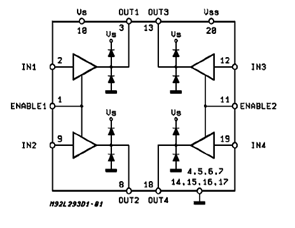
The L293D are quadruple high current half H drives. The L293D is designed to provide bidirectional drive current up to 600 mA at voltages from 4.5V to 36 V. Both drives are designed to drive an inductive load such as a relay, solenoid, DC and bipolar stepping motor, as well as high current/high voltage loads in positive supply applications. L293D consists of four inputs with amplifiers and output protection circuits. Drives are enabled in pairs, with drives 1& 2 enabled by 1,2 EN and drives 3 &4 enabled by 3,4 EN. When an enable input is high, the associated driver are enabled and their outputs are active and in phase with their inputs.
Power supply unit:
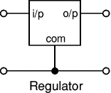
Low duty DC batteries comes with an appropriate voltage rating of 5V- 9V and a current of max. 1000mA. To obtain a regulated DC voltage, voltage regulators were used. Voltage regulator ICs are available with fixed (typically 5, 12 and 15V) or variable output voltages. They are also rated by the maximum current they can pass. Negative voltage regulators are available, mainly for use in dual supplies. Most regulators include some automatic protection from excessive current ( 'overload protection') and overheating ( 'thermal protection'). Many of the fixed voltage regulator ICs have 3 leads and look like power transistors, such as the 7805 (+5V, 1A) regulator shown on the right. They include a hole for attaching a heat sink if necessary.
Keil uVision software was used to develop the program for the 89C51 and Orcad Capture / Layout was used to design and fabricate our custom made PCB.
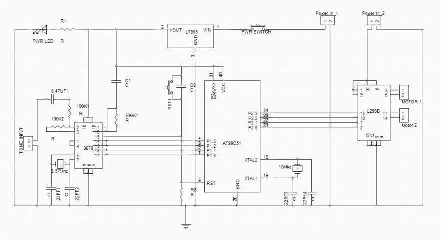
All types of the MT8870 series use digital counting techniques to detect and decode all the 16 DTMF tone pairs into a 4-bit code output. The built-in dial tone rejection circuit eliminates the need for pre-filtering when the input signal was given at pin 2 (IN-) in single-ended input configuration is recognized to be effective, the correct 4-bit decode signal of the DTMF tone is transferred via Q1(pin11) through Q 4(pin 14) output to the input pins P1.0(pin 1) to P1.3(pin 4) of port 1 of 89C51 IC. AT89C51 is the controlling unit. In this project, it accepts the binary code corresponding to the detected tone is received and the binary code to drive the motors will be sent to the driver IC. The output from port pins P2.0 through P2.3 of the microcontroller are fed to the input IN1 through IN4 of motor driver L293D, respectively, to drive two geared DC motors. A manual reset switch is also used. The microcontroller output is not sufficient to drive the DC motors, so current drivers are required for motor rotation. The L293D consists of four drivers. Pin IN1 through IN4 and out1 throughout 4 are input and output pins, respectively, of driver1 to driver4.
ALGORITHM FLOWCHART:
PROGRAM:
ORG 000H

START:
MOV P1,#0FH
MOV P2,#000H

L1: MOV A,P1
CJNE A,#04H,L2
MOV A,#0AH
MOV P2,A
LJMP L1

L2: CJNE A,#01H,L3
MOV A,#05H
MOV P2,A
LJMP L1

L3: CJNE A,#0AH,L4
MOV A,#00H
MOV P2,A
LJMP L1

L4: CJNE A,#02H,L5
MOV A,#06H
MOV P2,A
LJMP L1

L5: CJNE A,#06H,L1
MOV A,#09H
MOV P2,A
LJMP L1

END
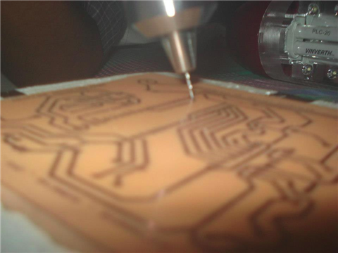
PCB FABRICATION:
The making of PCB was completed in 4 steps:
1. Component layout designing
2. PCB layout designing
3. Drilling
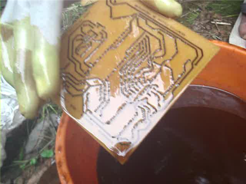
4. Etching the PCB
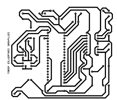
The PCB components were set up using the Orcad Capture software and were imported to Orcad Layout for designing the connections. The layout was then mirrored for printing on to the cleaned copper board. After the printing (we used a powder dye-based printer to print the layout onto a white paper and used an iron box to heat and transfer the impression on to the copper board surface. The extra copper was etched out using a ferric chloride solution and a small amount of hydrochloric acid was used as a catalyst. After the board was properly etched, the holes were drilled using a handheld PCB driller. The components were purchased and carefully soldered on to the board. As for the IC's, standoffs were first soldered upon which the IC's were placed.


For the robot to work as expected, we enabled automatic answering on the NokiaC1-02 mobile handset that we used as a receiver on the robot. So whenever somebody calls that number, the cellphone automatically answers. When the caller presses a tone switch, the receiver handset receives it and sends it to the DTMF decoder via audio out. The decoder decodes the key that was pressed and notifies the 89C51 microcontroller. The microcontroller then issues appropriate control commands to the robot via the motor drivers.