


1. Introduction
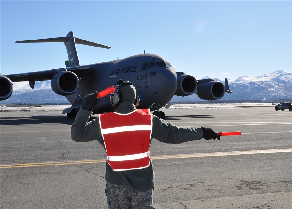
In aeronautics, marshalling is a one-to-one visual communication and is part of aircraft ground handling, as shown in image below
The idea for this project14 challenge is to build an automated marshal that will guide you while parking the car in your garage. I will use vision-based techniques to detect the plate number of the car. Then, the automated car marshal will provide visual indications to keep the car on the correct path and will warn when the stop position has been reached. The hardware components to build this project are
- An almighty Raspberry Pi 4 board
- A TFT display for Raspberry Pi: the 7" display will provide visual feedback when you are close enough to the stop position and can clearly see the display content
- A webcam: even if you can use a Raspicam, a USB webcam provides more freedom in terms of installation possibilities, so I choose this option
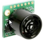
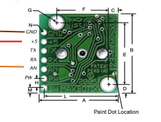
- A sonar: I have a MB1020 sonar module hanging around in my lab, so I decided to use this sensor to have a precise distance measure when the car is close to the stop position (less than 60 cm). When the car is farther than that, the distance is calculated from relative size of the number plate in the images captured by the webcam
- An Emlid Navio+ board: this was actually a later addition, along with the servos. The problem was MB1020 has inverted TTL serial signals. This means I should had to build a levels inverter circuit to connect the sonar sensor to the Raspberry Pi. However, the MB1020 also has an analog output. This brought me to the decision to use the Emlid Navio+, a very powerful (yet outdated) board designed for drone builders.
- two servo motors: servos was another later addition: since I am going to use the Emlid Navio+ board, and because the Emlid Navio+ board has so many PWM output channels, why not use them? Servos will mimic the gestures a marshal uses to give directions. The plan is to create an automated car marshal that can make the following signals
 |
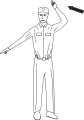 |
 |
 |
| Proceed straight | Turn left | Turn right | Stop |
Here is an overview of the hardware and the connections

2. Raspberry Pi4 setup
First, let's install all the software components required to build and run an Qt-based OpenCV application.
I started from a fresh Raspbian Buster image (I initially tried with Bullseye, but some OpenCV dependencies are missing in the repositories for this version, so I rolled back to Buster)
2.1 Preliminary operations
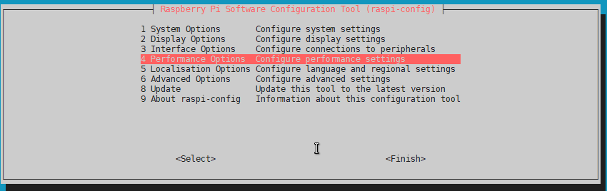
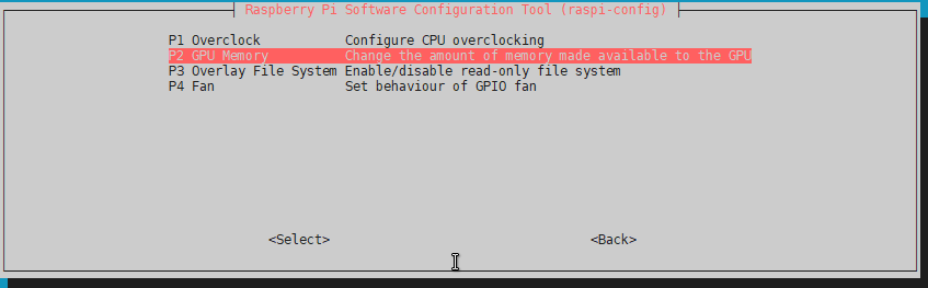
2.1.1 GPU memory size
The physical RAM chip is used both by the CPU and the GPU. The Raspberry Pi 4 has a 76 Mbyte GPU memory size. It can be somewhat small for vision projects, better to change this now to a 128 Mbyte. To increase the amount of memory for the GPU, use raspi-config.
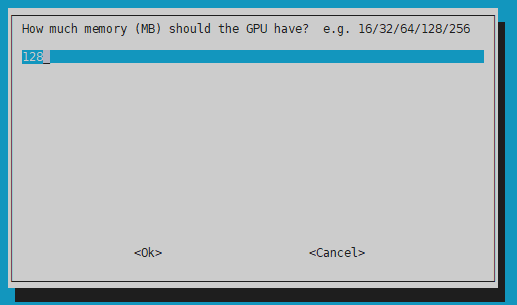
After this action, reboot the board
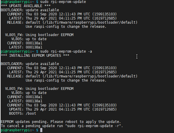
2.2.2 Update EEPRM
With a fresh and clean Raspbian operating system, the last check is the EEPROM software version. I was not aware that the Raspberry Pi 4 is partially booted from two EEPROMs (on the contrary, the Raspberry Pi 3 had all the operating software on the SD card). These EEPROMs are programmed after PCB assembly in the factory. The Raspberry Pi foundation has recently released new and improved software for these EEPROMs. Improvements have been made, among the other things, in heat dissipation. Since machine vision applications are CPU-intensive, it's a good idea to install this update because a low CPU temperature will prolong CPU lifespan. There are more information about firmware updates here
To update EEPROMs, run the following commands
- get the current status
sudo rpi-eeprom-update
- update if needed
sudo rpi-eeprom-update -a
- reboot
sudo reboot
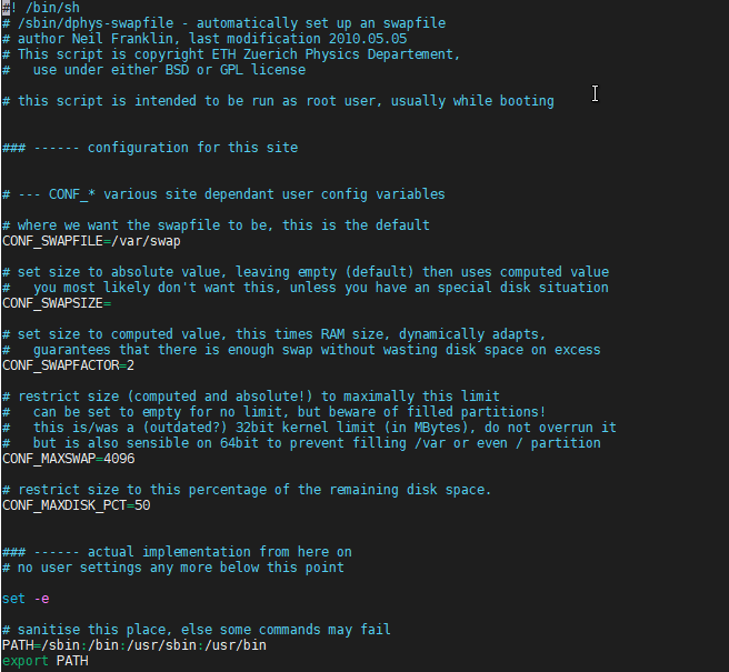
2.2.3 Increase swap size
OpenCV needs a lot of memory to compile. The latest versions want to see a minimum of 6.5 GB of memory before building. On Raspberry Pi4, swap space is limited to 2048 MByte by default. To exceed this 2048 MByte limit, you will need to increase this maximum in the /sbin/dphys-swapfile
sudo nano /sbin/dphys-swapfile
sudo nano /etc/dphys-swapfile
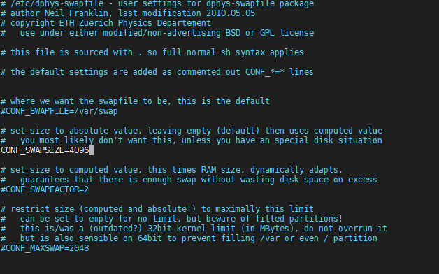
Reboot the board
2.1Installing Qt
Raspberry PI comes with an outdated version of Qt5 (5.11). Even if there are instructions to build and install Qt5.12 LTS from source, version 5.11 is enough for my purposes so I will just install the default version
sudo apt-get install qt5-default
2.2 Installing OpenCV
In this github repo there is a very useful script that executes all the commands to download, build ad install OpenCV
Here are the commands to run to install OpenCV 4.5.4
wget https://github.com/Qengineering/Install-OpenCV-Raspberry-Pi-32-bits/raw/main/OpenCV-4-5-4.sh
sudo chmod 755 ./OpenCV-4-5-4.sh
Edit the script at line 54 and change
-D WITH_QT=OFF
to
-D WITH_QT=ON
Finally run the script and wait for completion
./OpenCV-4-5-4.sh
3. Emlid Navio+ setup
3.1 Software setup
Setting up software for Navio+ board is quite easy: there is a github repository with all the source code required to build a library that provides access to the board's peripherals
git clone https://github.com/emlid/Navio2.git
cd Navio2/C++
make
In the Build folder, some example applications are built for a quick test of the hardware
3.2 Hardware setup
For this project, I am going to use
- ADC2 channel for the sonar
- 2 PWM output channels for the two servo motors
Even if ADC0 and ADC1 are easily available on the connector labelled "POWER", I didn't have a male connector that matched the connector on the board, so I soldered the sonar sensor wirings directly to the pads on the back of the board

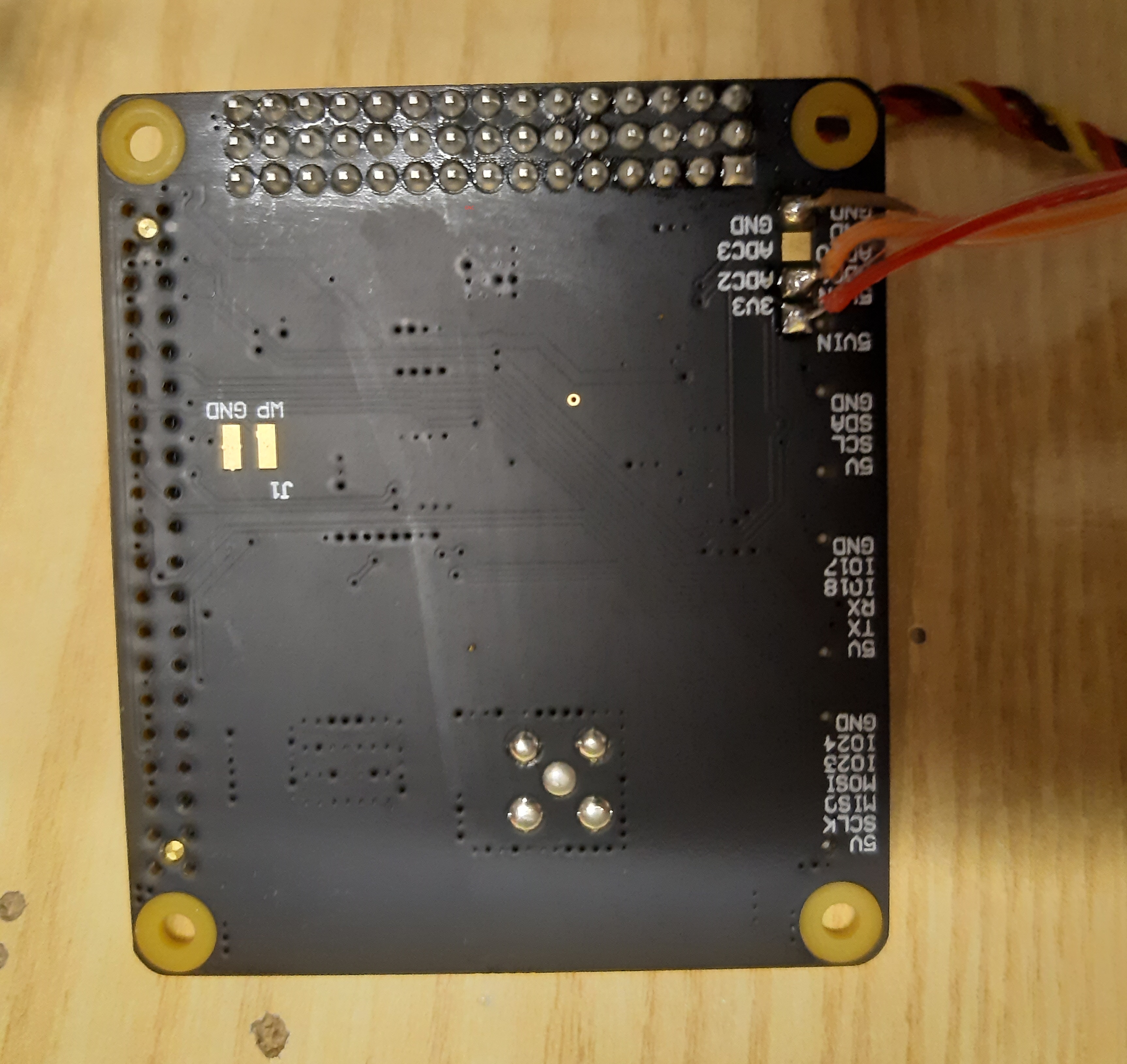
The two servos are connected to PWM output channels 1 and 2.
Here is an overview of the hardware

4. Plate detection
The initial plan was to learn something about realtime license plate recognition by leveraging some powerful technologies and tool like
- openalpr
- ssd (single shot detector)
- yolo (you only look once)
However this solutions were really overkilled for the application I had in mind and also led to a very poor number of frames processed per second (less the 1 fps), which is obviously unacceptable if you want to provide a realtime feedback to the driver
For this reason, I explored a more conventional openCV-based approach. I took inspiration for the plate detection algorithm from this project
The basic steps of the algorithm are
- image preprocessing
- detect possible chars
- group chars and sort groups by number of chars
- return the most probable plate
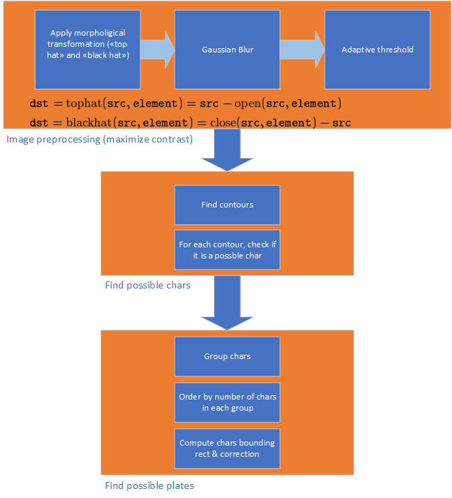
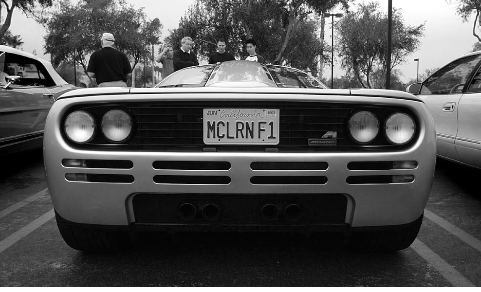
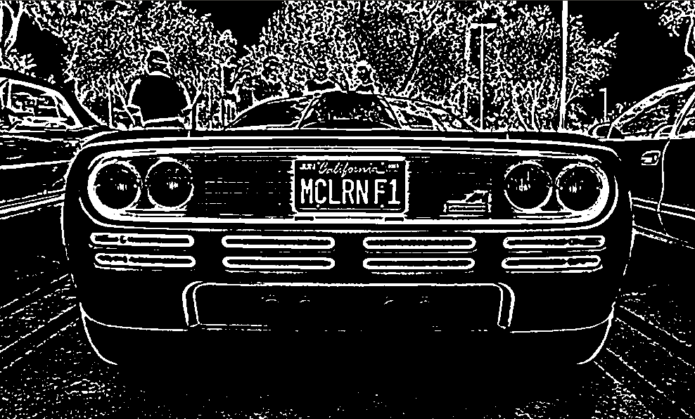
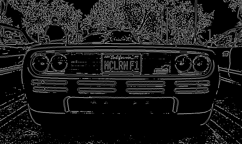
Here are some images that, better that one thousand words, explains how the processing pipeline works
4.1 Original image

4.2 Gray-scale image
4.3 Image with adaptive threshold
4.4 Contours
4.5 Contours of possible chars
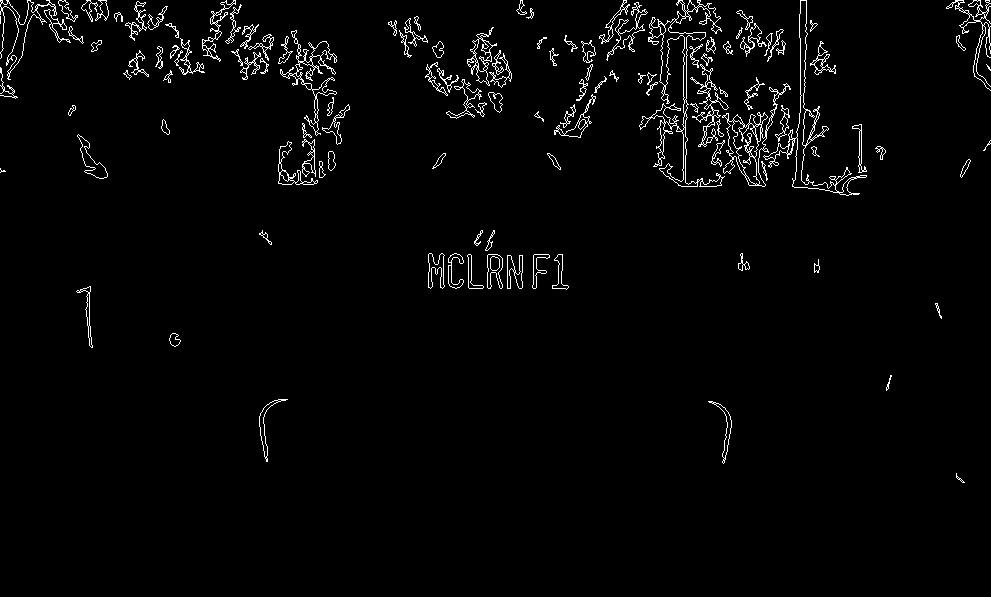
4.6 Detected chars
4.7 Plate bounding rectangle

5. Application
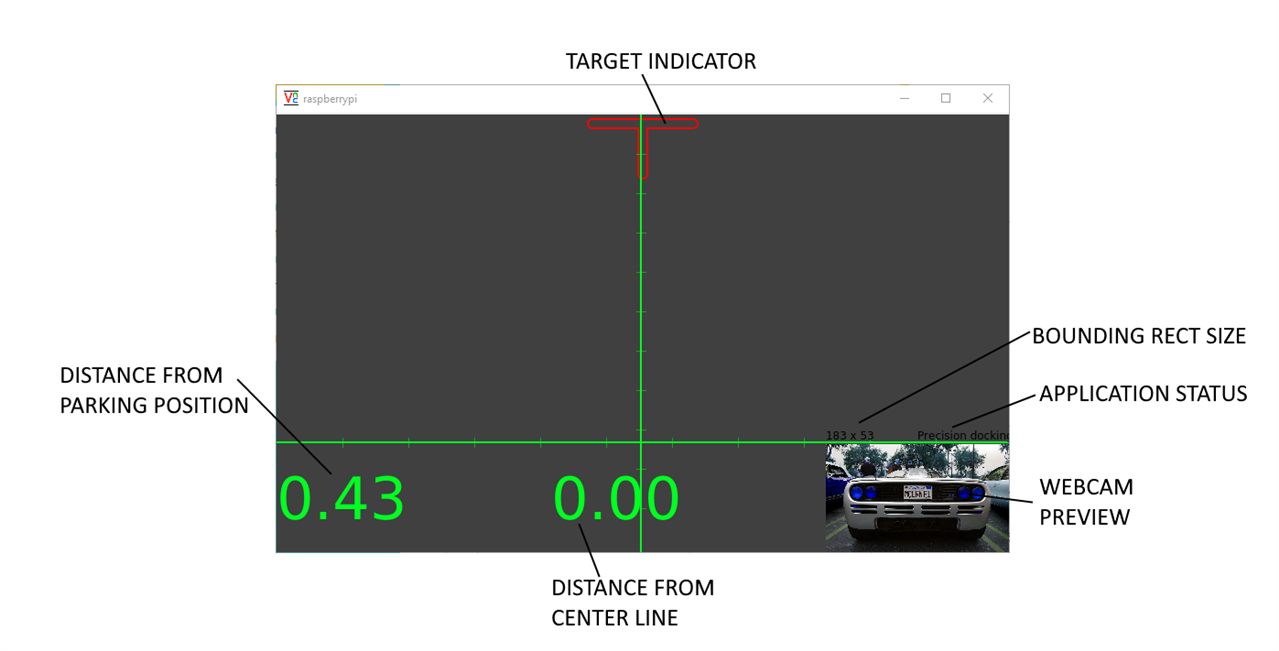
In this screenshot, information on the application user interface are shown
Application logic is shown in diagram below
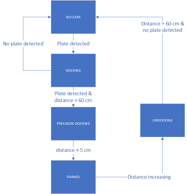
Here are more details about the states in the flow chart above
5.1 "No car" state
The application is initially in "No car" state. In this state, no plate is detected in the video stream captured by the webcam. Sonar sensor is not detecting any object as well
5.2 "Docking" state
Plate detection algorithm is continuously running against the video stream from the webcam. When a plate is detected, the state is set to "Docking", meaning that a car is approaching the parking slot. In the "Docking" state, distance from stop position is calculated based on the relative size of the plate. Distance from center line is calculated based on horizontal plate position in the image. Distance is calculated according to the following formula
#define PLATE_WIDTH_MM 360#define PLATE_DISTANCE_MM 1000#define PLATE_WIDTH_PIXELS 200 /* pixels of plate when placed at 1m */
double f = (PLATE_WIDTH_PIXELS * PLATE_DISTANCE_MM) / PLATE_WIDTH_MM; mDistanceY = (PLATE_WIDTH_MM * f) / boundingRectWidth;
Distance from the center line is calculated from the horizontal distance of the plate from the center of the image. A cursor is shown on the TFT screen and the marshal "arms" are move to provide visual feedback to the driver about the corrections to make to maintain the correct direction
5.3 "Precision docking" state
When the car is in the sonar detection range (about 60 cm from the stop position), application status is to "Precision docking". In this state, distance from stop position is read from sonar and is more precise than the distance calculated from relative plate size. As I already wrote, the sonar sensor is a Mobatix MB1020. This sensor as a TTL serial output the distance is transmitted on by means of simple ASCII messages. However, TTL signal is inverted (meaning that the serial "space" state is high instead of low). To connect such a sensor to the Raspberry Pi's serial would require a dedicated circuit to invert TTL signal back to standard levels. I chose for a more creative "solution": I am reading the analog output signal of the MB1020 sensor and compute distance from the voltage readouts. The signal level is somewhat erratic, so I had to implement a simple moving average algorithm to filter out peaks and show smooth distance values on the UI
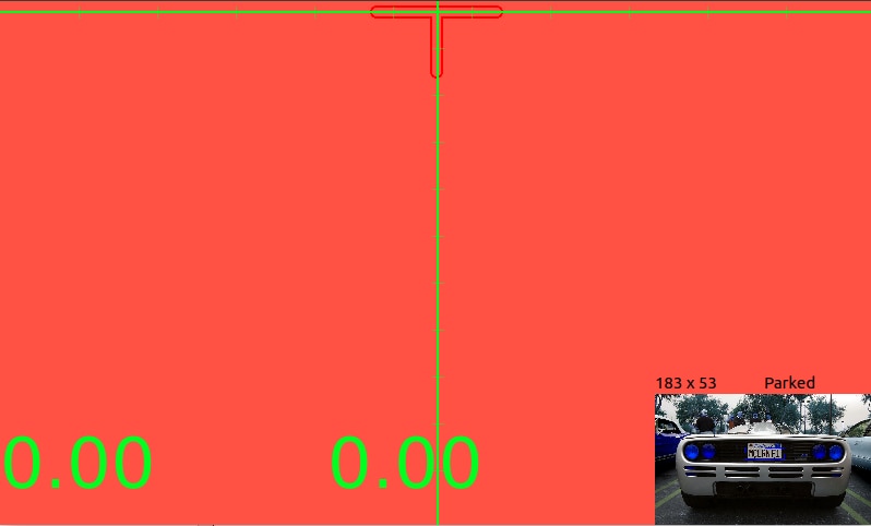
5.4 "Parked" state
When distance returned by the sonar drops below a given threshold, the application status is switched to "Parked" state. The TFT screen turns to red to warn the driver that the final position has been reached. Marshal "arms" are moved to a vertical position to provide a more incisive visual feedback
5.5 "Undocking" state
When distance returned by the sonar increases, the application status is switched to "Undocking" state, meaning that car is leaving the parking lot. Marshal "arms" move quickly to say goodbye to the driver. Finally, when nothing is in the sonar detection range and no plate is detected, the application returns back to "No car" state
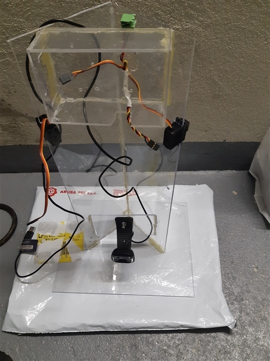
7. Construction
These are some pictures I took while I was building the automated car marshal. This is made of plexiglass glued with hot glue

6. Usage
The usage of the automated car marshal is very easy: you have to put the device in the position where the car is supposed to be parked. If you want to get a precise distance measurement when car is beyond sonar range, a simple calibration process needs to be followed
- park the car at 1 meter of distance from the automated car marshal
- on the UI, just above the video preview, read the width of the plate's bounding rectangle
- edit file mainwindow.cpp and, in the line replace the current value with the value you just read on the UI
#define PLATE_WIDTH_PIXELS 200 /* pixels of plate when placed at 1m */ - build and restart application
7. Demo
8. Source code
To build the application, please run the following commands
git clone https://github.com/ambrogio-galbusera/docking.git
cd docking
qmake -r docking.pro
make
To run the application
sudo ./docking <n>
where n is the video input device to use. To check the correct value, enter the command
ls /dev/fb*
You should see at least one device whose name is /dev/fb<n>. n is the argument to add to the application command line
9. Conclusions
As usual, challenges and projects on Element14 are good opportunities to think in a creative way and explore new technologies. And this project14 theme was not an exception. I discovered a lot of useful info, from some interesting details about the Raspberry Pi 4 platform to the technologies behind plate detection systems installed on our roads.
The project is still in an embryonic stage. For sure, some tuning of the plate detection algorithm is required to make the calculation of the bounding rectangle less erratic. Also, sonar readouts need a better filtering algorithm to remove noise on the analog signal. Other improvements are the use of a larger HDMI monitor instead of the 7" DSI monitor and the ability to switch on and off the LED strips
Hope you enjoyed this post, thanks for reading!
