


An ultrasonic range finder is a useful tool in a variety of real-life and robotic applications, such as in obstacle avoidance and distance measurement systems. The ultrasonic range finder measures the distance by emitting a 40KHz pulse of ultrasonic sound that travels through the air until it hits an object, then it measures the delay of the reflected signal and sends proper commands to other units.
I used an SRF05 ultrasonic sensor and an ATTiny85 microcontroller. The distance data is displayed on a 128*64 OLED screen, both in centimeters and inches. Also, a horizontal bar graph provides a visual estimation of the distance. The MCU code was developed using the Arduino IDE.
To design the schematic and PCB, I used Altium Designer 22 and SamacSys component libraries (Altium plugin). To get high-quality PCB boards, I sent the Gerbers to PCBWay and purchased original components using componentsearchengine.com. To examine the current consumption of the circuit, I used the Siglent SDM3045X multimeter.
Isn’t cool?! So let’s get started.
Specifications
Input Voltage: 6-24VDC
Current Consumption: 24mA
Detection Range: 2-400cm (see text)
Distance Data: Centimeters, Inches, Bar Graph
Display: 128*64-Yellow Blue OLED
Circuit Analysis
Figure 1 shows the schematic diagram of the ultrasonic range finder device. As it is clear, the circuit consists of four main parts: sensor, power supply, MCU, and display. I explain each part separately.
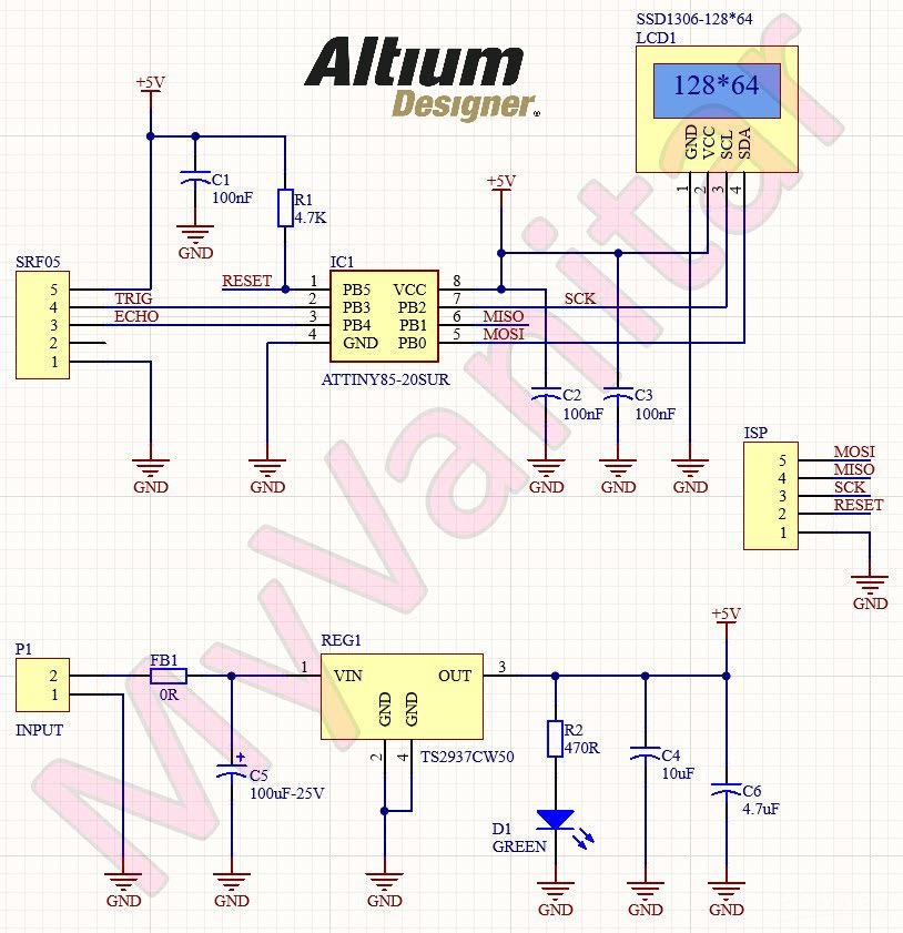
Figure 1
Schematic diagram of the ultrasonic range finder (Altium)
SRF05 Ultrasonic Sensor
I used an SRF05 ultrasonic module for the circuit. There are a variety of SRF05 modules in the market, I used the one that is shown in figure 2.
The quality of the modules might vary, so the maximum detection range can not be guaranteed. Some of them have blue solder-mask and some are green, also different manufacturers provide such modules.
According to the SRF05 module datasheet:” The SRF05 is an evolutionary step from the SRF04, and has been designed to increase flexibility, increase range, and to reduce costs still further. As such, the SRF05 is fully compatible with the SRF04. The range is increased from 3 meters to 4 meters. A new operating mode (tying the mode pin to the ground) allows the SRF05 to use a single pin for both trigger and echo, thereby saving valuable pins on your controller. When the mode pin is left unconnected, the SRF05 operates with separate trigger and echo pins, like the SRF04. The SRF05 includes a small delay before the echo pulse to give slower controllers such as the Basic Stamp and Picaxe time, to execute their pulse in commands.”

Figure 2
An SRF05 ultrasonic module (blue solder-mask)
Power Supply
The main component of the power supply is TS2937CW50 [1] regulator (REG1). It is a +5V SOT-223 LDO regulator. According to the TS2937 datasheet: “TS2937 of fixed-voltage monolithic micro-power voltage regulators is designed for a wide range of applications. This device excellent choice of use in battery-power applications. Furthermore, the quiescent current increases slightly at dropout, which prolongs battery life. This series of fixed-voltage regulators feature a very low ground current (200uA Typ.) and very low drop output voltage (Typ. 60mV at light load and 600mV at 500mA). This includes a tight initial tolerance of 2%, extremely good line regulation of 0.05% typ., and very low output temperature coefficient.”
FB1 and C5 reduce input voltage noises. D1 is a Blue 0805 LED to indicate a proper supply connection and R2 limits the current of D1. C4 and C6 are used to reduce the noises of the +5V supply rail. P1 is an XH-2P female connector to connect the supply wires to the board.
Microcontroller
IC1 is an ATTiny85 MCU [2], which is the heart of the circuit. I selected the SMD package of this chip. According to the Tiny85 datasheet: “The ATtiny25/45/85 provides the following features: 2/4/8K bytes of In-System Programmable Flash, 128/256/512 bytes EEPROM, 128/256/256 bytes SRAM, 6 general-purpose I/O lines, 32 general purpose working registers, one 8-bit Timer/Counter with compare modes, one 8-bit high-speed Timer/Counter, Universal Serial Interface, Internal and External Interrupts, a 4-channel, 10-bit ADC, a programmable Watchdog Timer with Internal Oscillator, and three software selectable power saving modes. Idle mode stops the CPU while allowing the SRAM, Timer/Counter, ADC, Analog Comparator, and Interrupt system to continue functioning. The power-down mode saves the register contents, disabling all chip functions until the next Interrupt or Hardware Reset. ADC Noise Reduction mode stops the CPU and all I/O modules except ADC, to minimize switching noise during ADC conversions. The device is manufactured using Atmel’s high-density nonvolatile memory technology. The On-chip ISP Flash allows the Program memory to be re-programmed In-System through an SPI serial interface, by a conventional non-volatile memory programmer, or by an On-chip boot code running on the AVR core.”
C1, C2, and C3 are decoupling capacitors and are used to reduce noises. R1 is a pullup resistor to avoid the unwanted triggering of the MCU’s RESET pin.
OLED Display
The display consists of a 0.96” 128*64 OLED module with an SSD1306 controller chip. The data/command interface of the module is I2C. figure 3 shows a picture of this module. I2C consists of SDA and SCL lines that need to be pulled up using two resistors. This module has already implemented the pullups, so there is no need to add more resistors on the line.
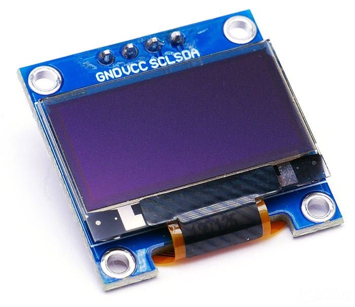
Figure 3
OLED Display of the device (0.96”, 128*64, I2C)
PCB Layout
Figure 4 shows the PCB layout of the circuit. It is a two layers PCB board and all components are SMD. The display should stand a few millimeters above the PCB to maintain a distance between the components and the backside of the display to avoid and short circuit, .. etc. The PCB is designed to be compact and easy to use.

Figure 4
The PCB layout of the ultrasonic range finder (Altium)
When I decided to design the schematic and PCB for this project, I realized that I don’t have the component libraries of REG1 [3] and IC2 [4] in my component libraries storage. So as usual, I selected IPC-rated SamacSys component libraries and installed the missing libraries (schematic symbol, PCB footprint, 3D model) using the free SamacSys tools and services. There are two ways to import the libraries: You can visit the componentsearchengine.com and download and import the libraries manually, or you can use the SamacSys CAD plugins and automatically import/install the libraries into the design environment. Figure 5 shows all supported electronic designing CAD software [5]. As it is clear, all famous players are supported. I use Altium Designer, so I installed the missing libraries using the SamacSys Altium plugin (Figure 6) [6]. Figure 7 shows a 3D view of the board and two assembly drawings of the PCB board.

Figure 5
All supported electronic designing CAD software by the SamacSys plugins

Figure 6
Selected component libraries in the SamacSys Altium plugin

Figure 7
A 3D view and two assembly drawings of the PCB board
Code
The code of the MCU is written as below. You need to install the ATTinyCore Board Manager [7] and select ATTiny25/45/85 (no bootloader) from the menu (Figure 8). Then select the Chip as ATTiny85 and Select 8MHz (Internal) for the clock source (Figure 9).
Then you need to install the NewPing [8] and Tiny4KOLED [9] libraries. After this just go to the “Sketch” menu and select “Export compiled binary” (Figure 10). That’s it. You can find the compiled HEX file in the same folder as your code exists. Just use an AVR ISP programmer (such as USBasp or whatever) to program the chip using the available pins on the backside of the PCB (GND, RESET, MISO, MOSI, SCK). Follow the procedure and program the fuse bits as shown in figure 11. Disconnect the programmer and wires from the board and that’s it :-).
#include <Tiny4kOLED.h>
#include <NewPing.h>


unsigned long uS = 0;


#define TRIGGER_PIN  3
#define ECHO_PIN     4
#define MAX_DISTANCE 41


NewPing sonar(TRIGGER_PIN, ECHO_PIN, MAX_DISTANCE);
unsigned int CM = 0, IN = 0;
unsigned char cnt = 0;


void setup() {
  oled.begin(128, 64, sizeof(tiny4koled_init_128x64br), tiny4koled_init_128x64br);
  oled.on();
  oled.setCursor(0, 1);
  oled.setFont(FONT8X16);
  oled.clear();
  oled.print("ULS Range Finder");
}


void loop() {
  uS = sonar.ping();
  CM = sonar.convert_cm(uS) + CM;
  IN = sonar.convert_in(uS) + IN;
  cnt ++;
  if (cnt == 10)
  {
    oled.setCursor(0, 2);
    oled.print(CM / 10);
    if (CM / 10 < 10)
    {
      oled.setCursor(9, 2);
      oled.print(" Centimeter ");
    } else
    {
      oled.setCursor(17, 2);
      oled.print(" Centimeter");
    }


    oled.setCursor(0, 4);
    oled.print(IN / 10);
    if (IN / 10 < 10)
    {
      oled.setCursor(9, 4);
      oled.print(" Inches ");
    } else
    {
      oled.setCursor(17, 4);
      oled.print(" Inches");
    }


    switch (CM / 10)
    {


      case 0:
        oled.setCursor(0, 6);
        oled.print(" [out of range] ");
        break;
      case 1 ... 4:
        oled.setCursor(0, 6);
        oled.print("==              ");
        break;
      case 5 ... 9:
        oled.setCursor(0, 6);
        oled.print("====            ");
        break;
      case 10 ... 14:
        oled.setCursor(0, 6);
        oled.print("=====           ");
        break;
      case 15 ... 19:
        oled.setCursor(0, 6);
        oled.print("=======         ");
        break;
      case 20 ... 24:
        oled.setCursor(0, 6);
        oled.print("=========       ");
        break;
      case 25 ... 29:
        oled.setCursor(0, 6);
        oled.print("===========     ");
        break;
      case 30 ... 34:
        oled.setCursor(0, 6);
        oled.print("=============   ");
        break;
      case 35 ... 39:
        oled.setCursor(0, 6);
        oled.print("=============== ");
        break;
      case 40 ... 41:
        oled.setCursor(0, 6);
        oled.print("================");
        break;
    }


    CM = 0;
    IN = 0;
    cnt = 0;
  }
  delay(10);
}

Figure 8
Selecting the proper chip series (ATTiny25/45/85 (no bootloader)) from the menu

Figure 9
ATTiny85 clock source selection (8MHz, Internal)

Figure 10
Where to find and export the HEX file (Sketch menu)

Figure 11
How to program the board using an AVR ISP Programmer
Assembly and Test
Figure 12 shows the assembled PCB board. I put a piece of double-sided sticky tape between the display and PCB to avoid any possible short circuit. As it is clear in the picture, the characters on the OLED screen are quite bright and vivid.

Figure 12
Assembled PCB board of the ultrasonic range finder
If you plan to power the board using a battery, then the current consumption of the device is important. So I used the Siglent SDM3045X benchtop multimeter [10] and measured the current as 24mA. Figure 13 shows the multimeter screen.

Figure 13
The current consumption of the ultrasonic range finder circuit
Bill of Materials
Figure 14 shows the bill of materials for the project.

Figure 14
Bill of materials
References
[1]: TS2937CW50 datasheet: https://www.taiwansemi.com/assets/uploads/datasheet/TS2937_E15.pdf
[2]: ATTiny85 datasheet: http://ww1.microchip.com/downloads/en/DeviceDoc/Atmel-2586-AVR-8-bit-Microcontroller-ATtiny25-ATtiny45-ATtiny85_Datasheet.pdf
[3]: TS2937 schematic symbol, PCB footprint, 3D model: https://componentsearchengine.com/part-view/TS2937CW-5.0%20RP/Taiwan%20Semiconductor
[4]: ATTiny85 schematic symbol, PCB footprint, 3D model: https://componentsearchengine.com/part-view/ATTINY85-20SUR/Microchip
[5]: Electronic designing CAD software plugins: https://www.samacsys.com/library-loader-help
[6]: Altium Designer plugin: https://www.samacsys.com/altium-designer-library-instructions
[7]: ATTinyCore Arduino Board Manager: https://github.com/SpenceKonde/ATTinyCore
[8]: Arduino New Ping library: https://bitbucket.org/teckel12/arduino-new-ping/wiki/Home
[9]: Arduino Tiny4KOLED library: https://www.arduino.cc/reference/en/libraries/tiny4koled
[10]: Siglent SDM3045X multimeter: https://siglentna.com/digital-multimeters/sdm3045x-digital-multimeter/