Introduction:
Solar power is the key source of green emission free energy. Every day, the sun gives us free of cost energy which is far more than we need to power everything on our earth. Solar power is widely used as a sole power source in off grid data gathering equipment or remote network nodes. So before and after the installation of such important equipment we always need to know how much power our solar panel is providing and also how much our DC-to-DC converters (pmic, bms, buck/boost charger) are losing and what is our load. It will not only enable us to detect any fault in our remote system but also enable us to calculate the next maintenance schedule. As this system is not part of actual equipment and will be added to monitor everything. Therefore we need ultra low power sensors and controllers to gathers this data.
The sensors and micro-controller used in this project are chosen by keeping low power consumption in mind. The Maxim MAX32660 is one of lowest power consuming cortex M4F MCU. And Texas Instruments INA219 is also one of the lowest power consuming bidirectional high side current/voltage monitoring device. The graphical user interface is designed in NI LabView also shown below.
Components:
Hardware:
Ultra Low Power MAX32660 board
Multiple Power Monitoring (INA219) Modules
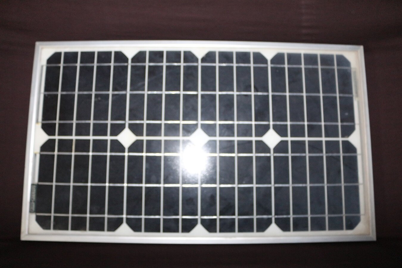
Solar Panel
DC to DC Module for Solar Energy Harvesting
Software:
ARM MDK or Eclipse Based IDE with Maxim MAX32660 SDK
LAB View
Circuit Diagram:
Two INA219 high side voltage and current sensors are connected at separate hardware I2C interfaces of MAX32660. The details of all the connections between INA219, Solar panel outputs, DC-to-DC converter and load are shown below.

ARM MDK Code:
We are using multiple INA219 sensors to measure the current and voltage so in programming we have two options to interface with MAX32660. First is use the INA219 serial bus address selector pins to assign the different address each sensor (upto 16) and then use a single I2C interface for all these sensors. The other option is keep the address of each sensor same and use different hardware I2C interface of mcu for each sensor. Here I have used 2 sensor with same serial address and different mcu I2C interface for each sensor. INA219 c library and main.c along with hex file that I used in this project is attached below.
First we will define and initialize the both the hardware I2C interface of MAX32660.
#define I2C_MASTER_0    MXC_I2C0
#define I2C_MASTER_1    MXC_I2C1
#define I2C_MASTER_ID0    0
#define I2C_MASTER_ID1    1
#define I2C_TIMEOUT    MXC_DELAY_MSEC(1)
Multiple hardware I2C interface initialization of MAX32660.
int error;
const sys_cfg_i2c_t sys_i2c_cfg = NULL; /* No system specific configuration needed. */
I2C_Shutdown(I2C_MASTER_0);
I2C_Shutdown(I2C_MASTER_1);

if((error = I2C_Init(I2C_MASTER_0, I2C_FAST_MODE, &sys_i2c_cfg)) != E_NO_ERROR) {
    printf("Error initializing I2C%d.  (Error code = %d)\n", I2C_MASTER_ID0, error);
    return 1;
}
NVIC_EnableIRQ(I2C0_IRQn);

if((error = I2C_Init(I2C_MASTER_1, I2C_FAST_MODE, &sys_i2c_cfg)) != E_NO_ERROR) {
    printf("Error initializing I2C%d.  (Error code = %d)\n", I2C_MASTER_ID1, error);
    return 1;
}
NVIC_EnableIRQ(I2C1_IRQn);
Now declare and initialize the INA219 sensors
easy_INA219 ina219_1;
easy_INA219 ina219_2;
ina219_1.ina219_i2caddr=INA219_ADDRESS;
ina219_1.i2c=I2C_MASTER_0;
ina219_begin(&ina219_1);
ina219_setCalibration_16V_400mA(&ina219_1);

ina219_2.ina219_i2caddr=INA219_ADDRESS;
ina219_2.i2c=I2C_MASTER_1;
ina219_begin(&ina219_2);
ina219_setCalibration_16V_400mA(&ina219_2);
Code for reading the sensor values and sensing it to the Lab-View over Virtual Serial Com port is very simple as shown below:
shuntvoltage = ina219_getShuntVoltage_mV(&ina219_1);
mxc_delay(MXC_DELAY_MSEC(10));
busvoltage = ina219_getBusVoltage_V(&ina219_1);
mxc_delay(MXC_DELAY_MSEC(10));
current_mA = ina219_getCurrent_mA(&ina219_1);
mxc_delay(MXC_DELAY_MSEC(10));
power_mW = ina219_getPower_mW(&ina219_1);
mxc_delay(MXC_DELAY_MSEC(10));
loadvoltage = busvoltage + (shuntvoltage / 1000);

printf("%.2f|%.2f|%.2f|%.2f|%.2f_", busvoltage, shuntvoltage, loadvoltage, current_mA, power_mW);

shuntvoltage = ina219_getShuntVoltage_mV(&ina219_2);
mxc_delay(MXC_DELAY_MSEC(10));
busvoltage = ina219_getBusVoltage_V(&ina219_2);
mxc_delay(MXC_DELAY_MSEC(10));
current_mA = ina219_getCurrent_mA(&ina219_2);
mxc_delay(MXC_DELAY_MSEC(10));
power_mW = ina219_getPower_mW(&ina219_2);
mxc_delay(MXC_DELAY_MSEC(10));
loadvoltage = busvoltage + (shuntvoltage / 1000);

printf("%.2f|%.2f|%.2f|%.2f|%.2f\r\n", busvoltage, shuntvoltage, loadvoltage, current_mA, power_mW);

LED_Toggle(0);    // Toggle the Onboard LED
mxc_delay(MXC_DELAY_MSEC(1000));    // 1 sec delay
Labview VI:
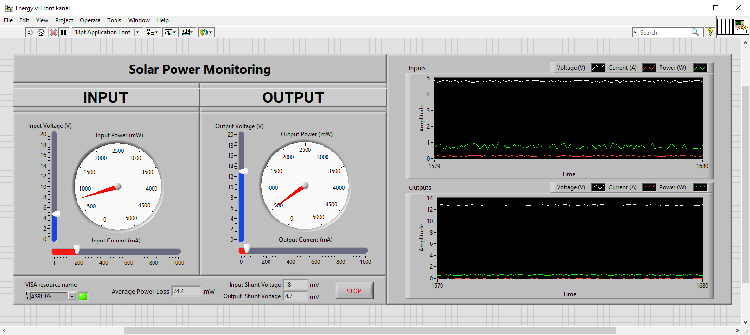
Front Panel:
In Lab-View the front panel GUI consist of Numeric and Boolean indicators along with waveform charts. All the controls are used with default settings except the fews. The ones with different setting are explained below.
The display format of the three numeric indicator displaying the Average Power Loss (moving average of 100 values), Input and Output shunt voltages is changed to increase the consistency among front panel numeric values. The changed display format is shown below.

The appearance of a Boolean indicator displaying the status of virtual serial communication is changed to show the green color when input is false (no error) and red when input is true (error).

The display format of numeric gauges displaying the Input and Output Power is changed to display the integer values only on its scale.

The display format of only X-axis of waveform chart in Labview front panel is altered as shown below or you can choose the Decimal as Time(X-Axis) Data type,

Block Diagram:
Labview block diagram is used to process the data/information and then it is provided to front panel indicators and controls. In the block diagram of this project a single while loop is used to process serial data every second. And shift register are you to build a FIFO to calculate the moving average of input and output power values. These average values are then used to calculate the average power loss between solar panel output power and DC-to-DC convertor output power as shown below. The component of block diagram inside black outline are used to initialize the array of the size of moving average window (100 values) and components inside the green outlines are used to build a FIFO array and moving average calculation.

The block diagram components inside a light blue color outline are waveform chart and multiple numerical values to cluster converter.

The virtual comport error or exception handling components are shown inside the light blue color outline. whenever there will any error occur in reading or communicating with MAX32660 this will stop the while loop automatically and also display the corresponding LAB-View error. The Error Code indicator is made invisible and its property node is used to make it visible in-case of any error.
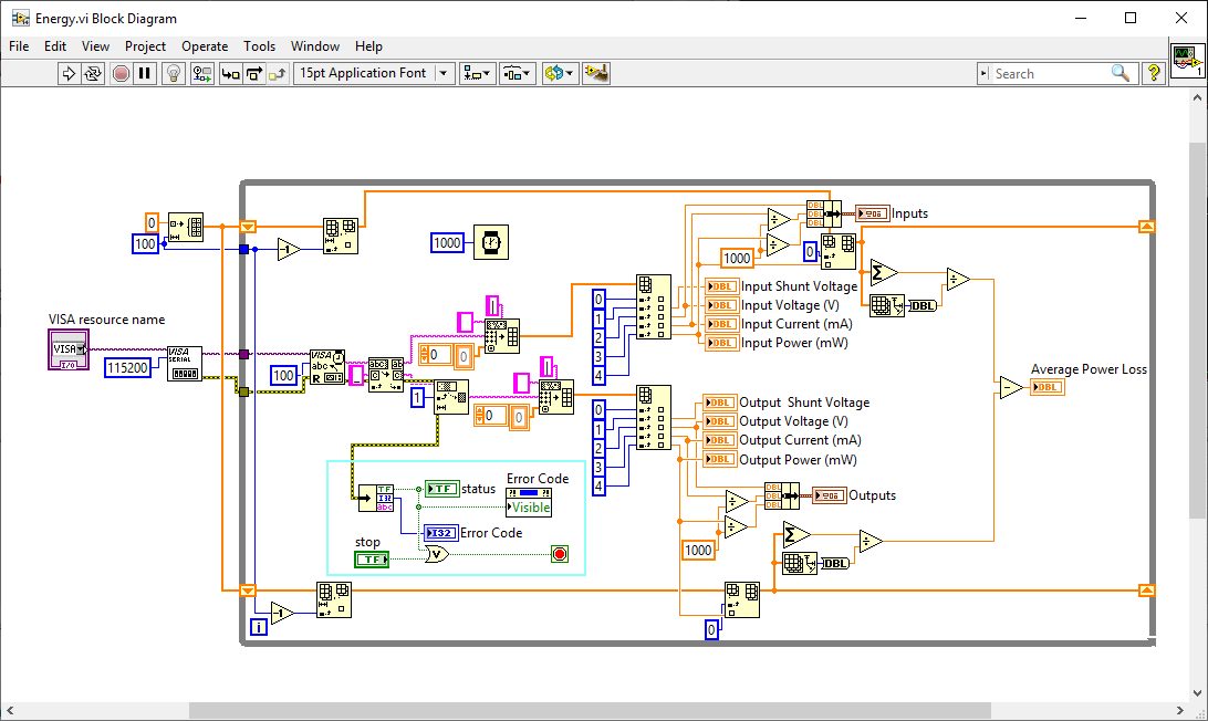
The block diagram component handling all the serial data are shown inside the red outline and also shown below. These are array handling components and first these will split the received string into two separate string containing all the values of each INA219 sensor. Then string of each sensor data is converted into numerical values array. In the last step, numerical array values are split into individual values.

All the numerical indicator displaying values of each INA219 sensor are shown inside maroon outlines.

GUI v1.0:


Demo:
Images:
| {gallery} Eagle EYE |
|---|
IMAGE TITLE: Solar Power Monitoring System |
IMAGE TITLE: Small Solar Panel |
IMAGE TITLE: Power Monitoring when Solar Panel is Connected with Boost Module |
IMAGE TITLE: LABview Front Panel |
IMAGE TITLE: LabView Block Diagram |