This project blog post is also the Part of PSoC
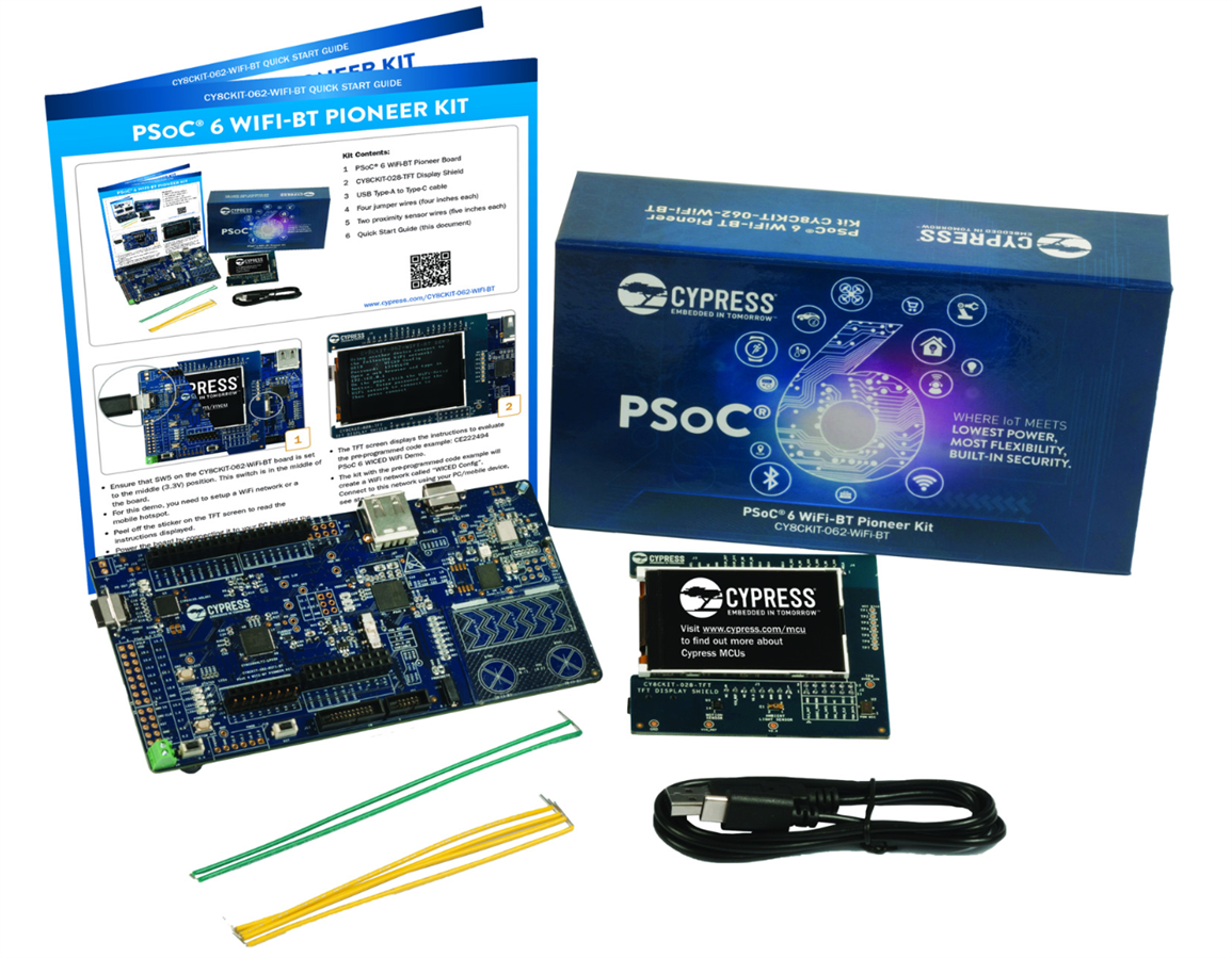
6 WiFi-BT Pioneer Kit (CY8CKIT-062-WIFI-BT) - Review Product LinkProduct Link (Figure 1). This post is also related to previous ones so for better understanding kindly take a look at those too.
Figure 1: PSoC6 WiFi-BT Pioneer Kit (details)
In the previous posts we have learnt how to successfully build and test different programs for PSoC6 using Cypress PSoC Creator, WICED Studio and Modus Tool Box. Now we will learn how to built an IOT Project using WICED Studio.
Building an IOT Project
In this project we will use Adafruit IO platform as mqtt broker, to store data and remotely interact with our PSoC device. And then add triggers to turn ON or OFF the LED light based on ambient light sensor value for easy and autonomous control of our remote device. Also designed a simple GUI for TFT LCD display for easy to understandable information display. This project can also be used with any other mqtt broker by just replacing the broker, feeds and client ID information and also adding the username and KEY if required. (Also Tested with IBM bluemix)
Main features of this project are;
- ON/OFF the RGB LED light.
- Control the Brightness of LED
- Choose the Color of RGB Light
- Ambient Light Sensor Monitoring
- Activity Viewer (TFT LCD Display)
WICED Studio has all the necessary libraries required to built any IOT project. In this project MQTT and Ugui (Graphics) libraries are used. All the steps required to built this project are given below and project files are also attached.
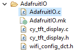
The project directory contains main .c file, .mk file along with TFT display driver .c & .h files and custom wifi configuration file for this project as shown below.
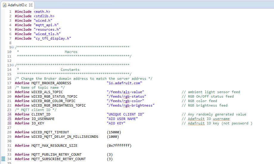
To connect with any MQTT broker we need its address, feeds path and unique client ID. For secure connection we need some additional information like username and key (not the password). All the required information to connect with Adafruit IO is shown below.
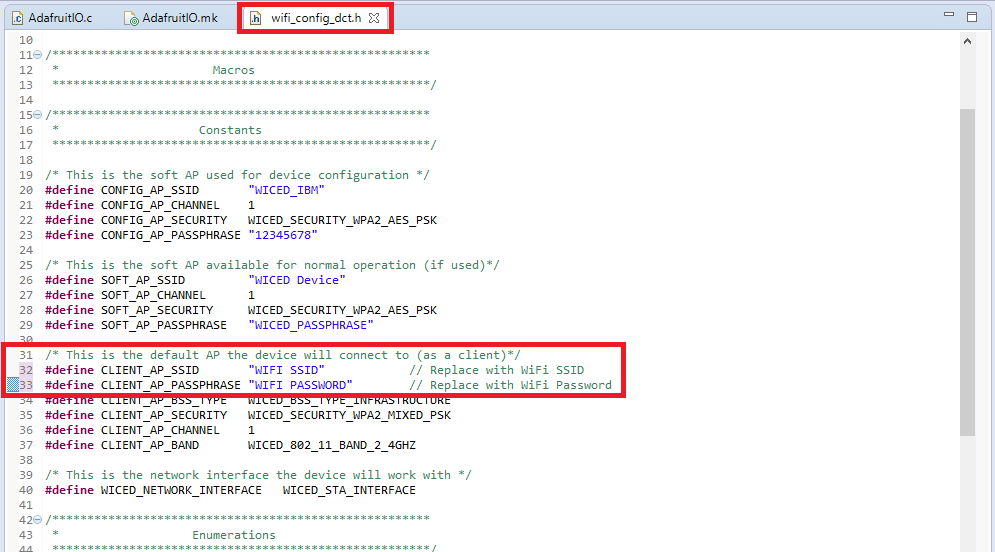
We can only connect with any MQTT broker if we have access to any network. In this project WiFi network is used for internet access and to connect with remote MQTT broker. We can also add the WiFi network settings in >include/default_wifi_config_dct.h and it can be used by every project. But in out project we used custom header file to keep its access to our project only.
After making the above mentioned changes we can build and run it on PSoC6 kit.
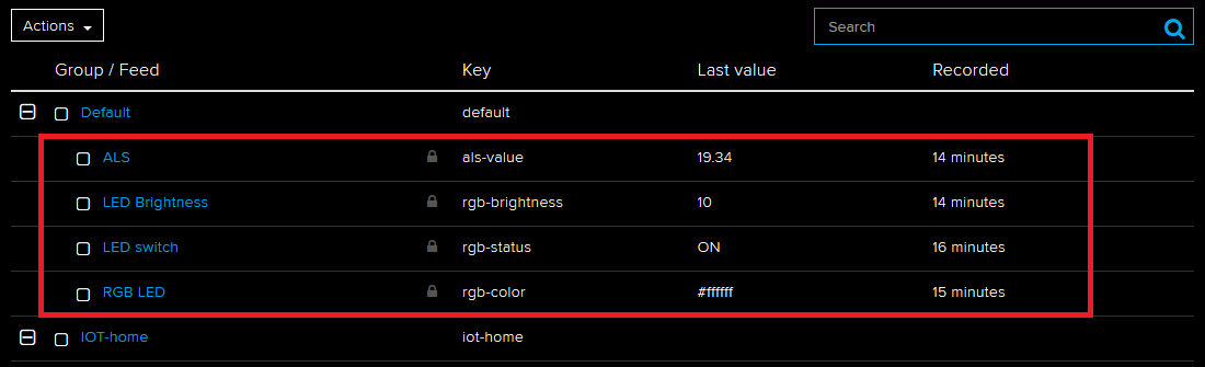
To interact with MQTT broker we need to create feeds and a GUI to interact with our device remotely. On Adafruit IO create four feed in default group as shown below. Any unique name can be used for these feeds. The only requirement for successful communication is using the same feed names in both PSoC code and AIO.
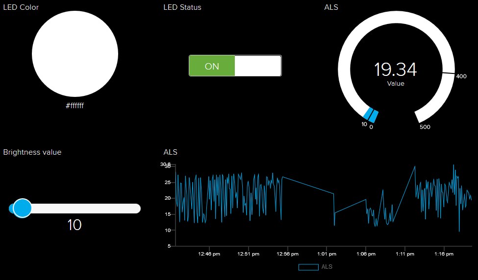
After creating the required feeds, create a new dashboard using these feed for interactive remote operation of PSoC device.
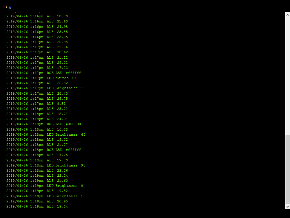
During debugging and testing we can also add the log widget to view all four feeds (up to 5 feeds) in AIO dashboard.
To add remote triggers based action, create trigger using on board ambient light sensor value to turn on or off the RGB led remotely without any user intervention.
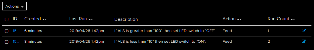
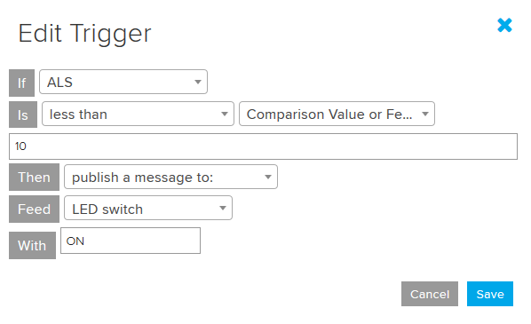
To turn on the LED create new trigger on ALS feed and choose publish a ON message to LED switch as its action if its value is less than 10 (any other value can be used).
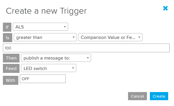
To turn off the LED create another trigger on ALS feed and choose publish a OFF message to LED switch as its action if its value is greater than 100 (any other value can be used).
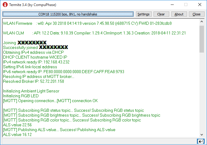
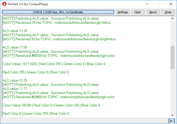
After downloading the program on PSoC6 kit we test all the communication between device and remote MQTT broker using UART monitor or on board TFT Display.
UART monitor showing WiFi network information and all the communication happening between device and remote mqtt broker.
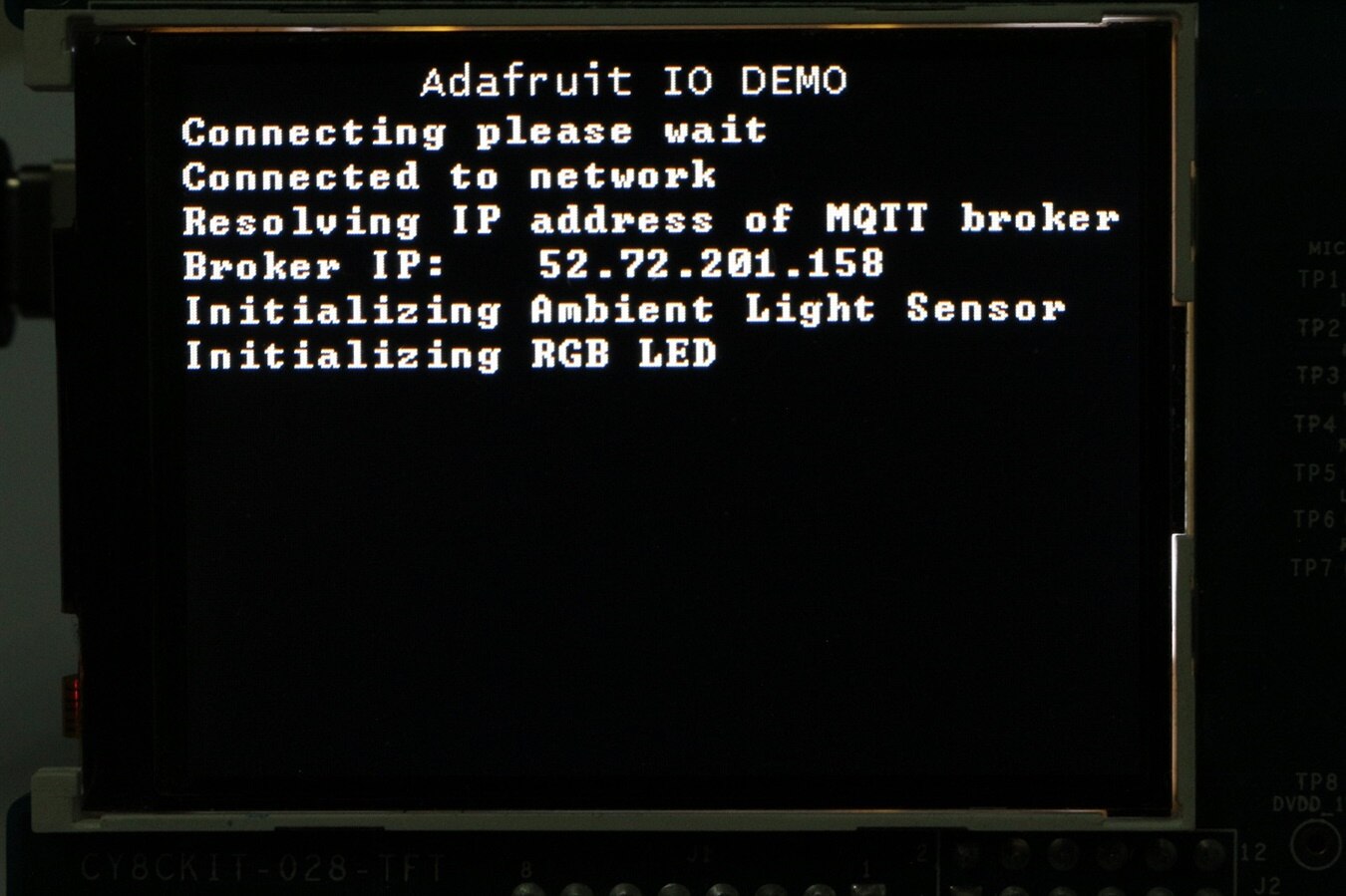
Similar information is also displayed on TFT LCD display but with less details. Device initialization and WiFi network details displayed on TFT LCD display are shown below.
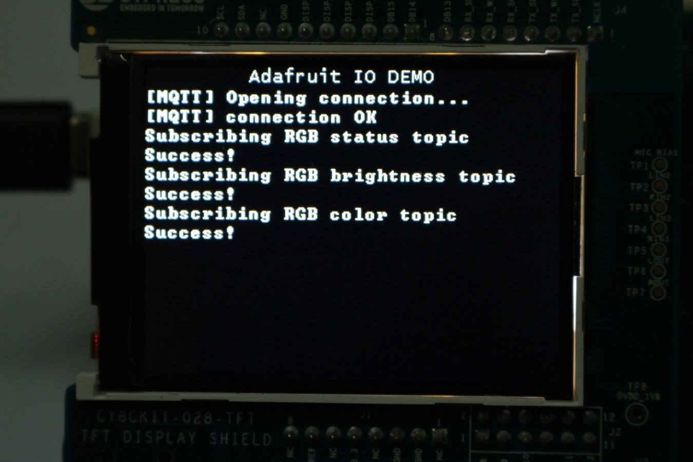
After successfully device and WiFi network setup, the initialization of communication and its status between device and MQTT broker is displayed as shown below.
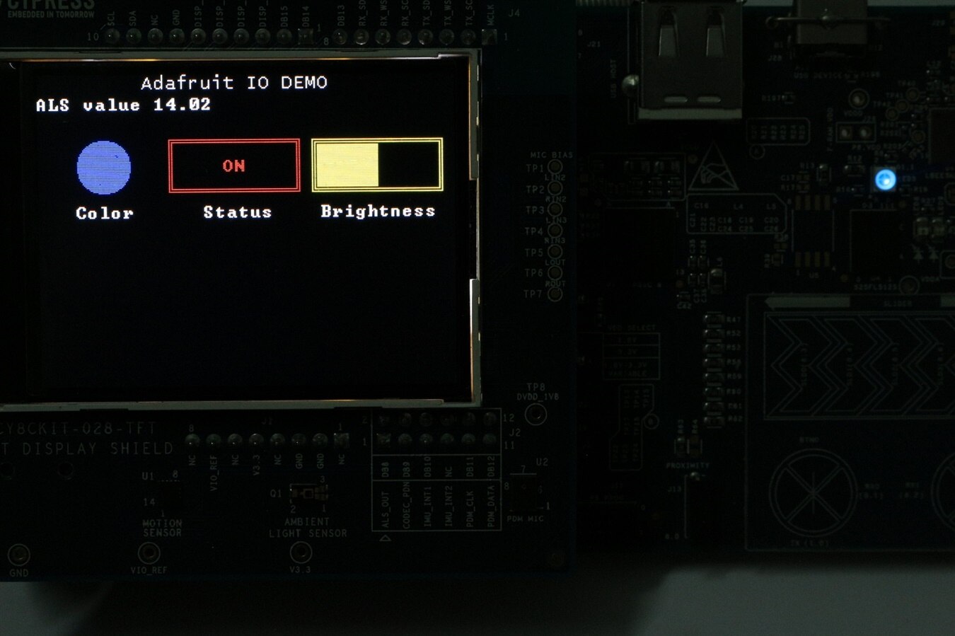
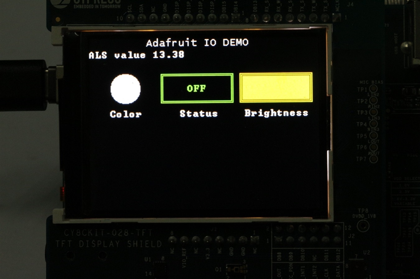
When communication and subscription of required MQTT feed is successful the main GUI is displayed on TFT LCD as shown below. At startup RGB led is OFF with white color and maximum brightness settings but these can be changed through AIO dashboard without turning ON the LED.
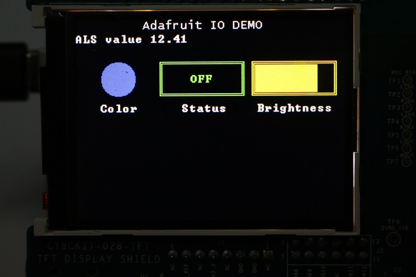
LED color is set to Blue and brightness level to 90% before turning the RGB LED.
Demo
Auto turn ON of LED light when ALS values goes below certain (10lx) level using Adafruit IO triggers.
Auto turn OFF of LED light when ALS values goes above certain (100lx) level using Adafruit IO triggers.
Gallery
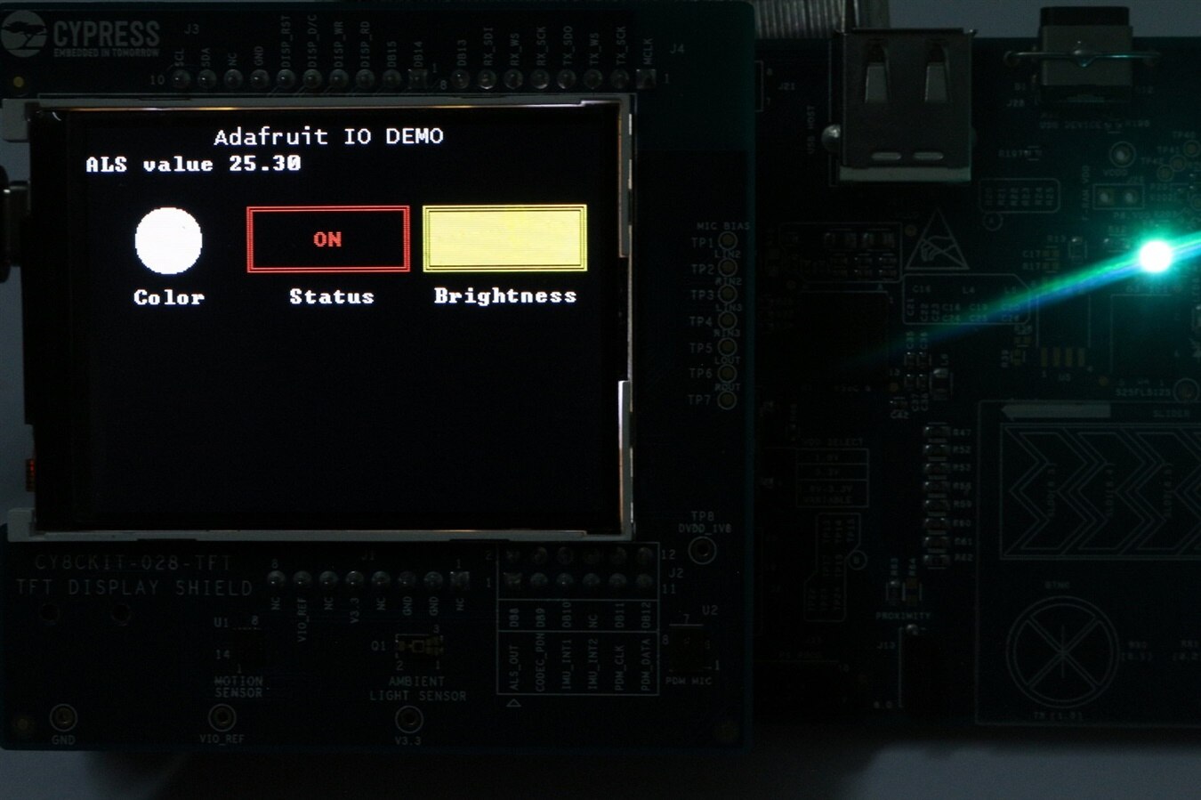
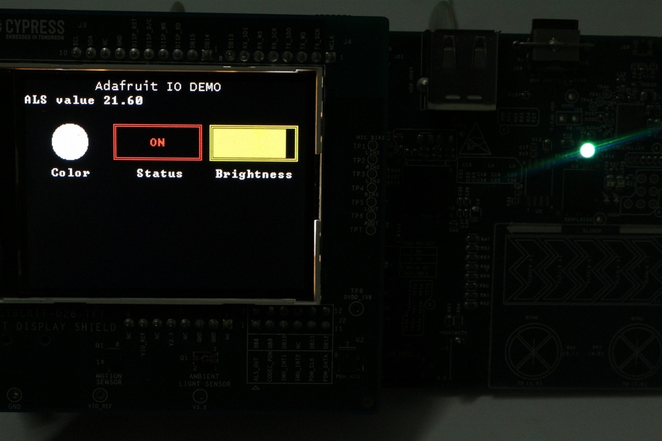
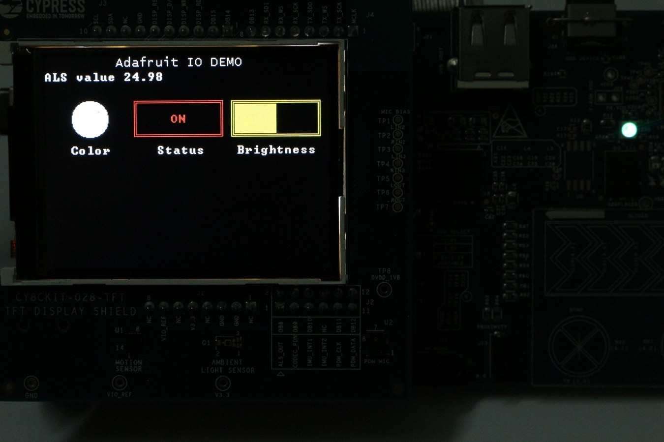
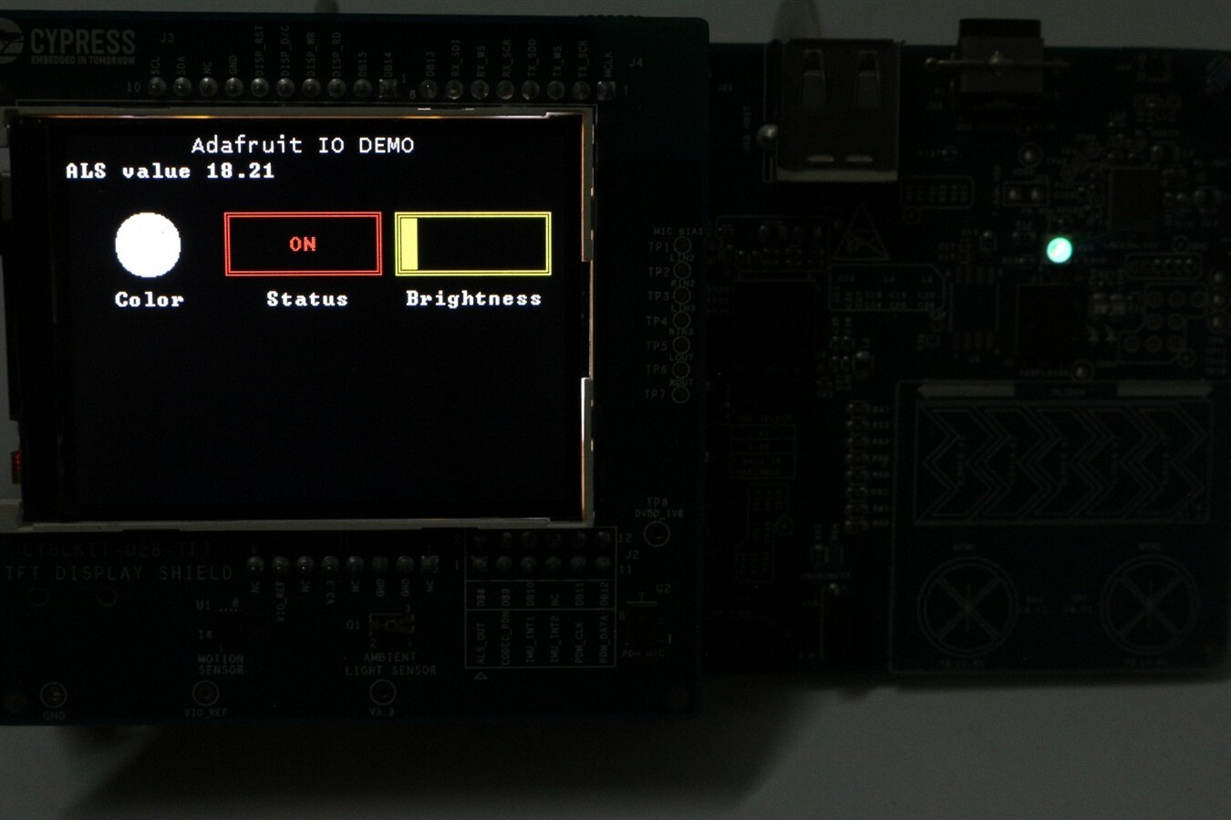
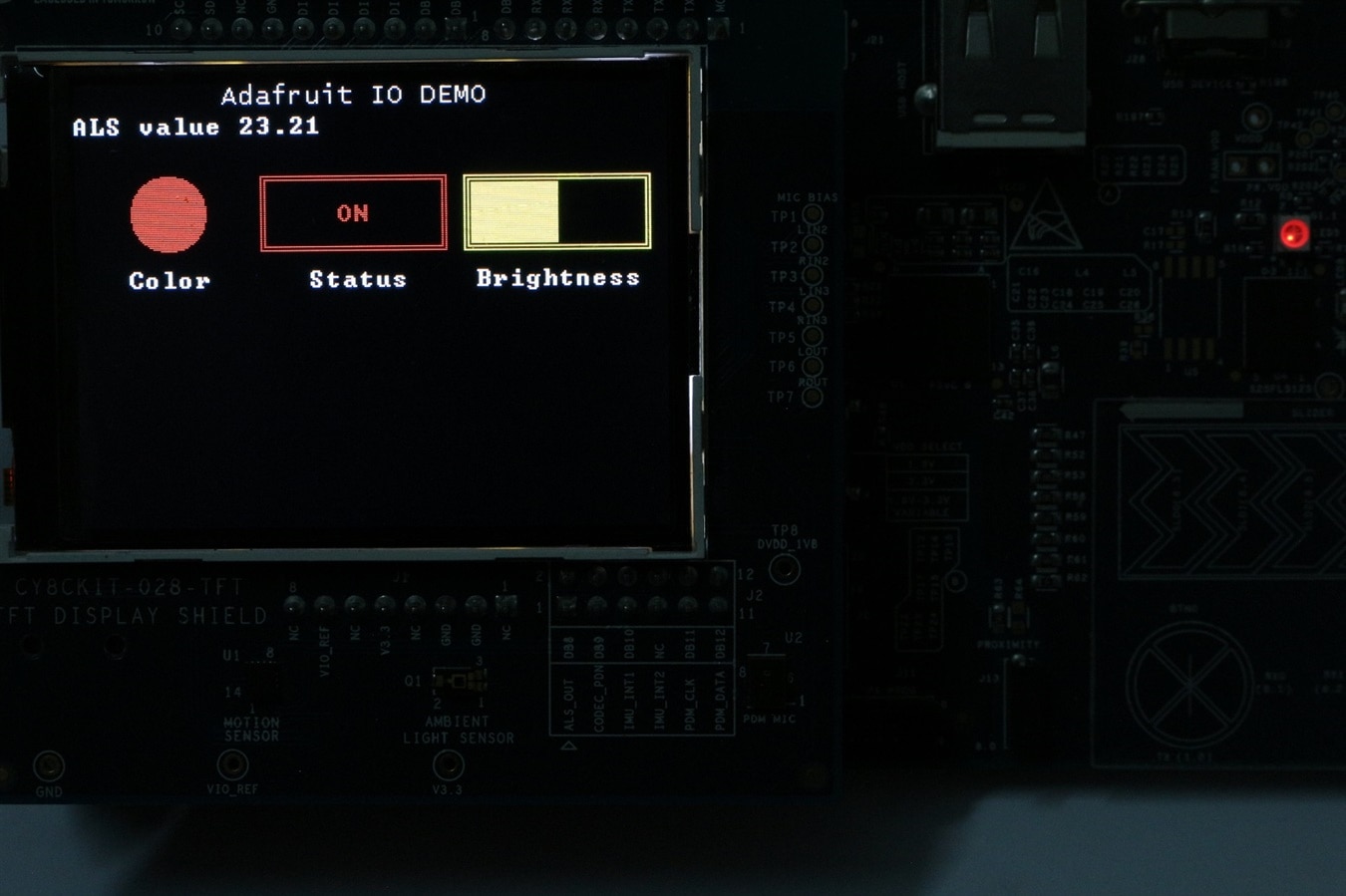
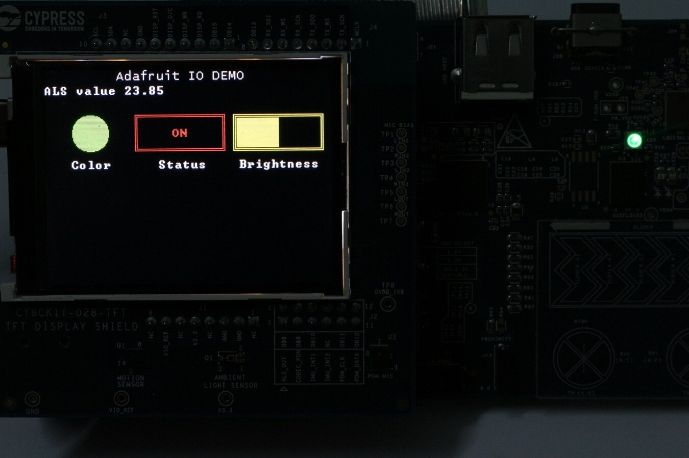
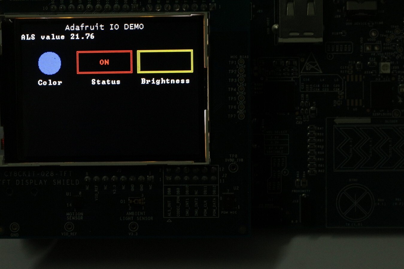
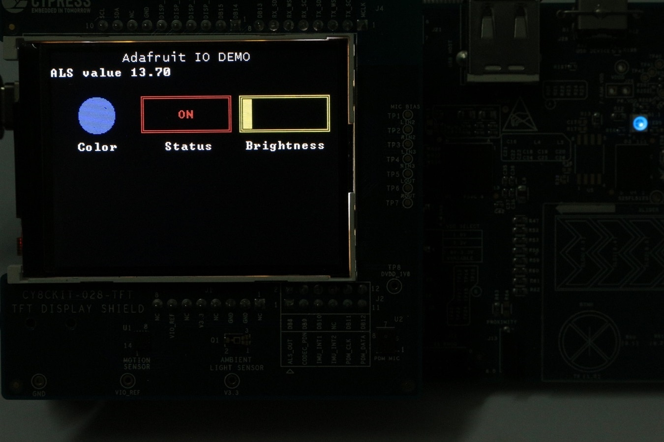
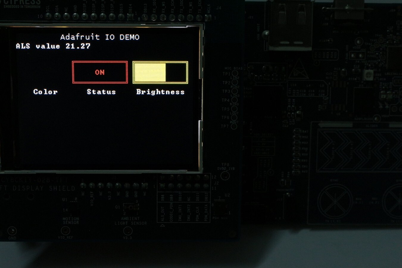
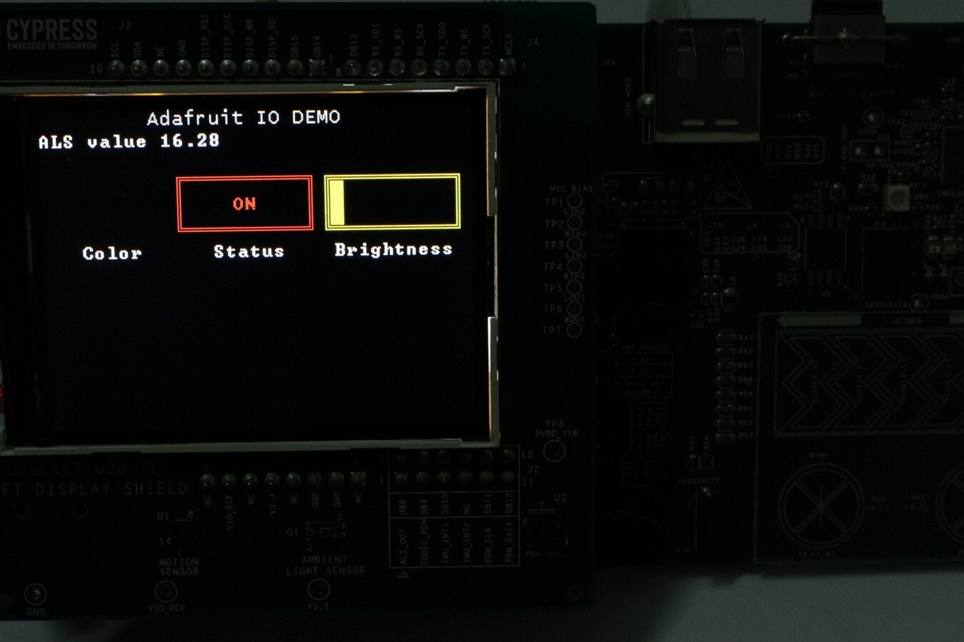
Image gallery with different LED colors and brightness settings along with respective values displayed on GUI.
| {gallery} PSoC 6 WiFi-BT Pioneer Kit - IOT Project DEMO |
|---|
IMAGE TITLE: LED Set to White Color and Maximum Brightness |
IMAGE TITLE: LED Set to White Color and High Brightness |
IMAGE TITLE: LED Set to White Color and Half Brightness |
IMAGE TITLE: LED Set to White Color and Low Brightness |
IMAGE TITLE: LED Set to RED Color and Half Brightness |
IMAGE TITLE: LED Set to Green Color and Half Brightness |
IMAGE TITLE: LED Set to Blue Color and No Brightness |
IMAGE TITLE: LED Set to Blue Color and Low Brightness |
IMAGE TITLE: LED Set to Blue Color and Half Brightness |
IMAGE TITLE: LED Set to Black Color and Medium Brightness |
IMAGE TITLE: LED Set to Black Color and Low Brightness |
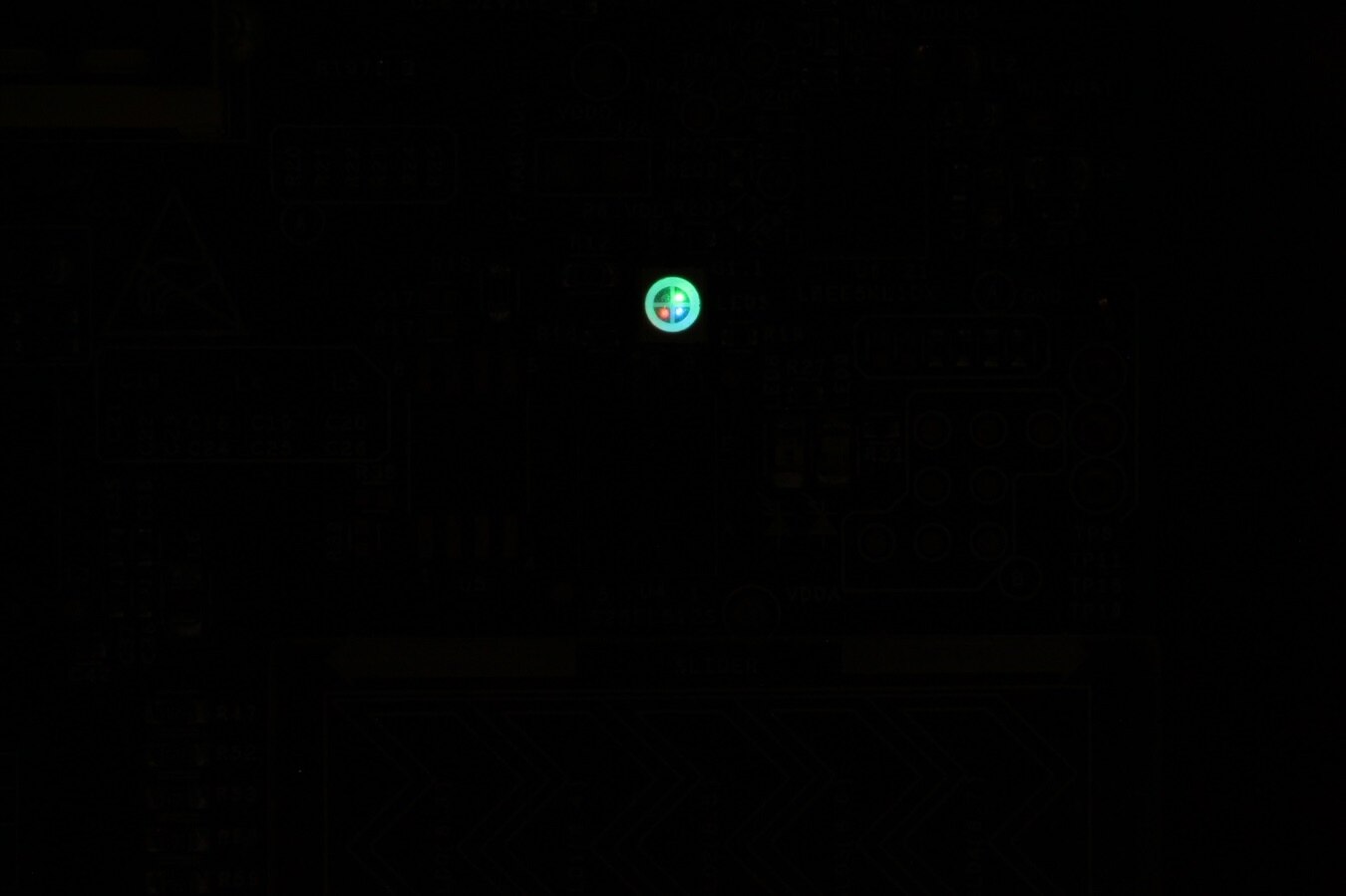
IMAGE TITLE: RGB LED Closeup View While Set to White Color and Low Brightness |