


Introduction:
Here I present the details of my project Smart Little/Special Child Safety Watch which is a part of Join the Challengers: Build a Smarter World: Build an Arduino MKR WAN 1300 Project for an Arduino Engineering Kit!.
Project proposal: Smart Little/Special Child Safety Watch
The problem statement and purpose solution detail can be found on above link.
Hardware:
The hardware used for both smart watch and Home control solution is described below;
Smart Watch:
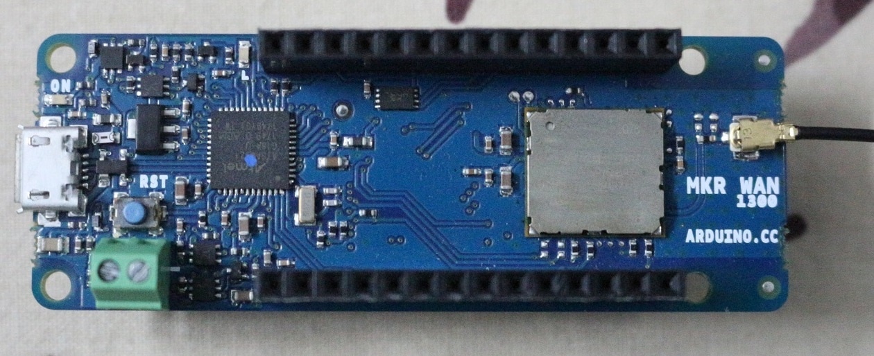
- Arduino MKR WAN 1300 (provided by ELEMENT14 community)
- 0.96inch oled display
- ESP8266 module with base
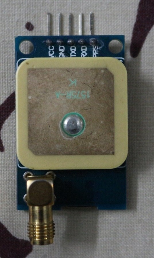
- NEO-6M GPS module
Base Station:
- Arduino MKR WAN 1300 (provided by ELEMENT14 community)
- Arduino MKR Relay shield (provided by ELEMENT14 community)
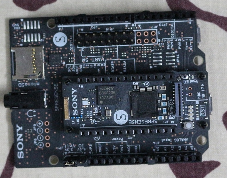
- Sony spresense dev + EXT. board
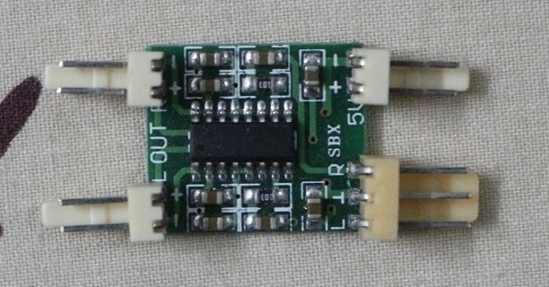
- PAM8403 amplifier board
- Speaker
- ESP8266 module with base
| {gallery} Main HW |
|---|
IMAGE TITLE: Arduino MKR WAN 1300 |
IMAGE TITLE: Arduino MKR Relay Shield |
IMAGE TITLE: ESP8266 module with base |
IMAGE TITLE: NEO-6M GPS Module with antenna |
IMAGE TITLE: NEO-6M GPS Module with antenna |
IMAGE TITLE: SONY Spresense dev + EXT board |
IMAGE TITLE: PAM8403 amplifier board |
IMAGE TITLE: Speaker |


And various other common components include 3.3V regulator, veroboard, 0.1" pitch female and male headers, 0.1" pitch connector, wires, buttons etc.
System Overview:
Smart Watch:
To achieve our main purpose RT tracking using smart watch, both GPS and WiFi module are incorporated for effective tracking.
The Arduino MKR WAN 1300 of smart watch is responsible for;
- Display info on OLED display
- RTC
- Communication with base station through its LORAWAN module
- Geo location info from GPS
- Communication with ESP8266 WiFi module
- Battery monitoring
- And user inputs.
And the ESP8266 WiFi module is used to connect with home network and data sharing with base station (if its available) and continues WiFi scan for approximate Geo location. The overall system diagram of smart watch is shown in figure 1-1.
figure 1-1. system overview of smart watch
Base Station:
The base station is consist of Arduino MKR WAN 1300 with relay shield, Sony spresense with Ext. board and ESP8266 modules, with amplifier and speaker to alert the parents. Extra feature of music player is also added in the base station to make it cool and fun project. The Arduino board is main control center of base station and it is responsible for all the communication between smart watch, spresense and esp8266 modules. Sony spresense is used for offline data storage, base station Geo location info and music/emergency sound player. Esp8266 is used for WiFi communication for easy configuration and online data sharing. The complete base station working diagram is shown in figure 1-2.
figure 1-2. system overview of base station
Development:
Hardware:
Smart Watch:
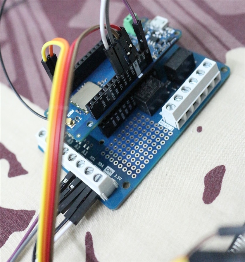
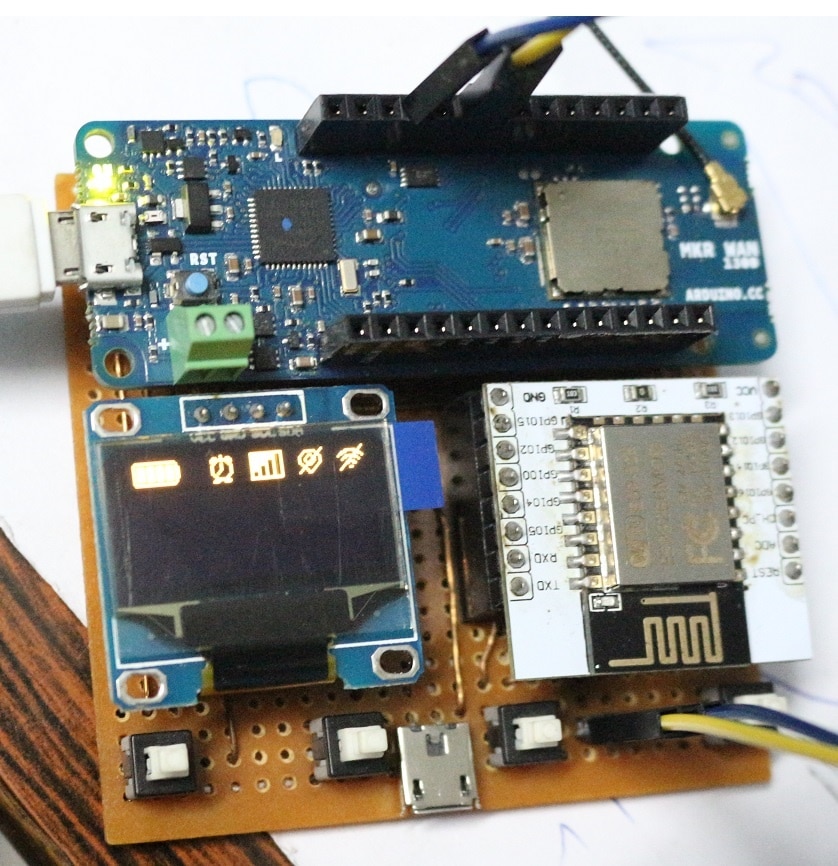
After basic testing of Arduino MKR WAN 1300 individually and with oled display, gps and ESP8266 module, several breadboard configuration were tested till finalizing the circuit Fritzing diagram shown in figure 2-1. And final veroboard circuit with and without hardware is also shown in figure 2-2, 2-3, 2-4 and 2-5. Jumper wires are used for ESP8266 module programing using Arduino board and also for serial communication with it during testing and operational verification.
figure 2-1. fritzing diagram of smart watch circuit
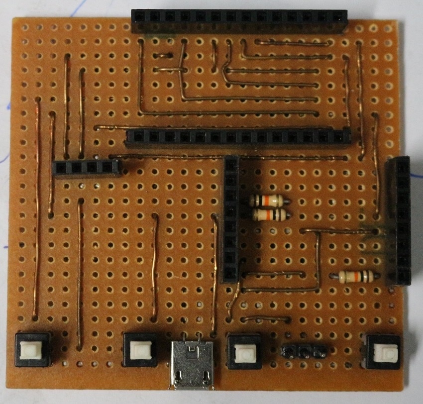
figure 2-2. veroboard circuit of smart watch (top view)
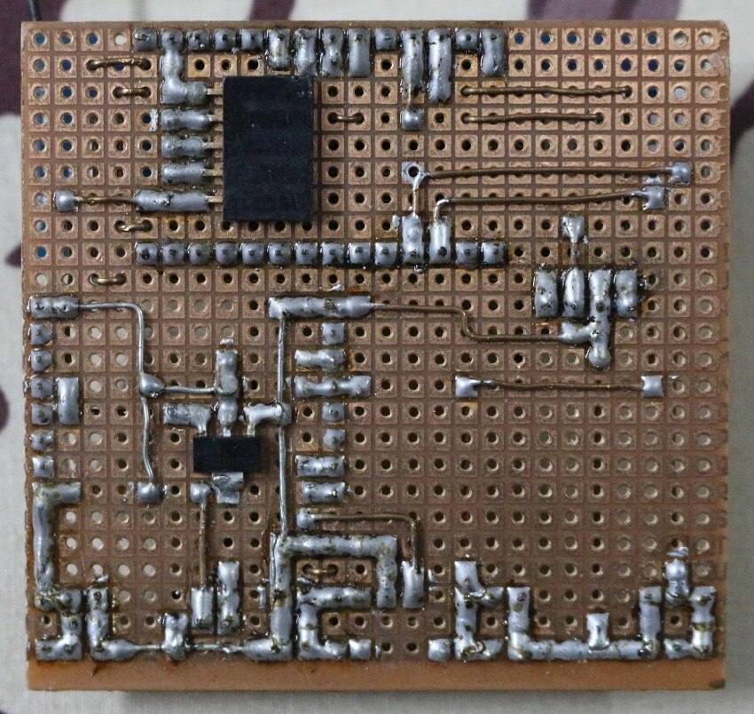
figure 2-3. veroboard circuit of smart watch (bottom view)
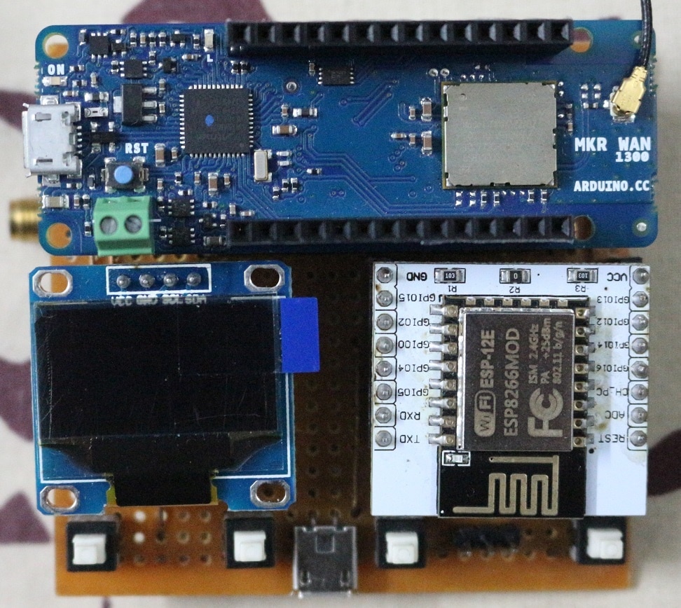
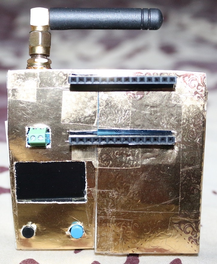
figure 2-4. complete hardware of smart watch (top view)
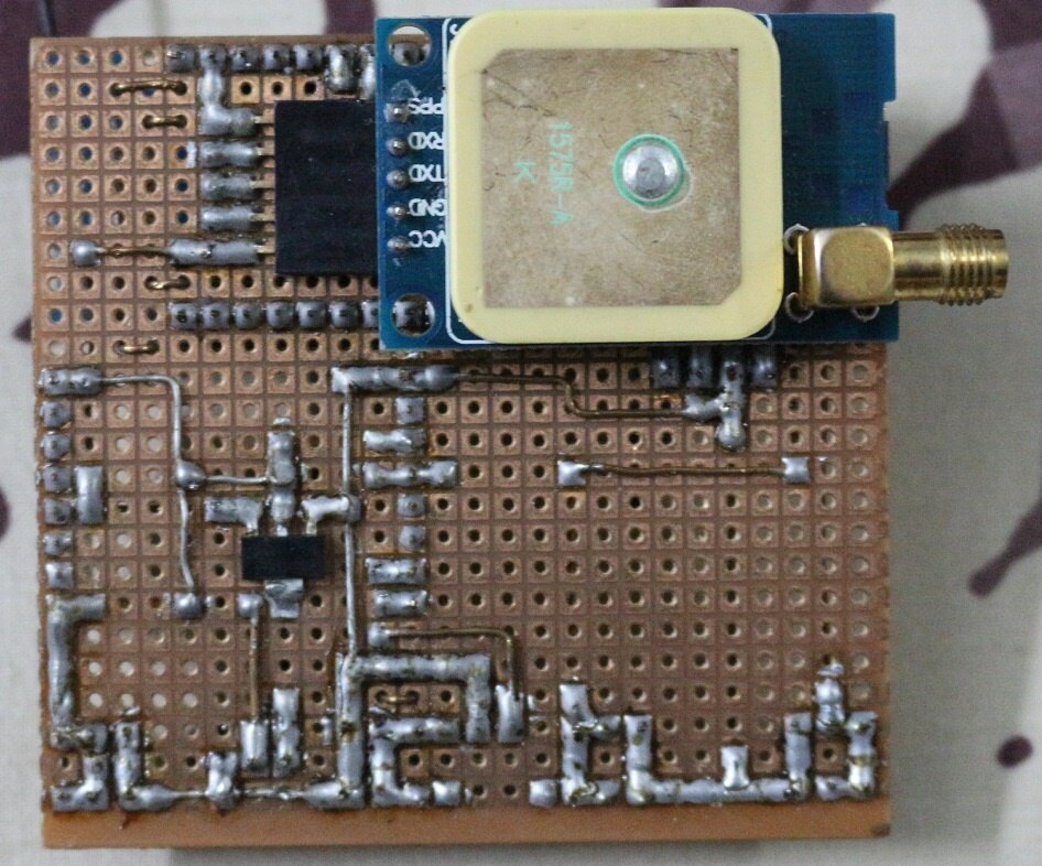
figure 2-5. complete hardware of smart watch (bottom view)
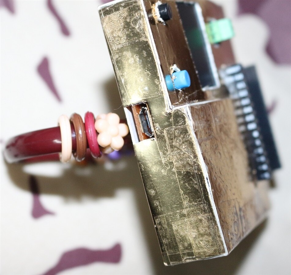
2pin Micro USB connector is added for easy powering up of the entire circuit instead of Arduino USB connector. GPS module used in this circuit is designed for 5V VCC with onboard 3.3V regulator.
Base Station:
figure 2-6. fritzing diagram of smart watch circuit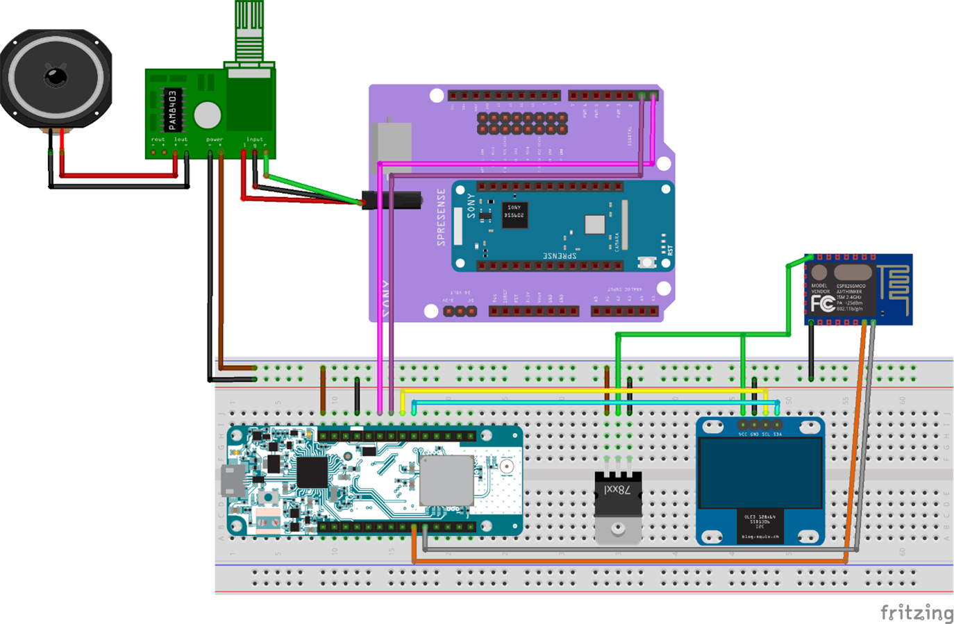
| {gallery} Base Station Hadware Assembly |
|---|
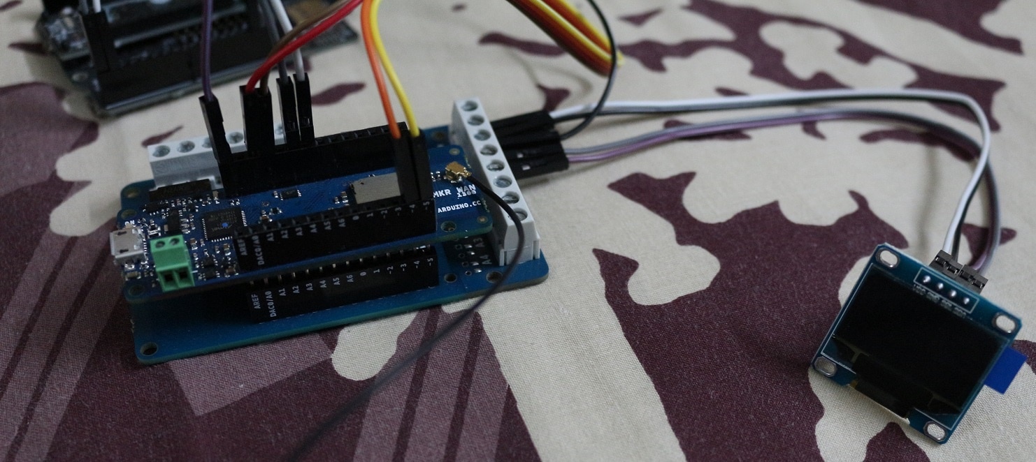
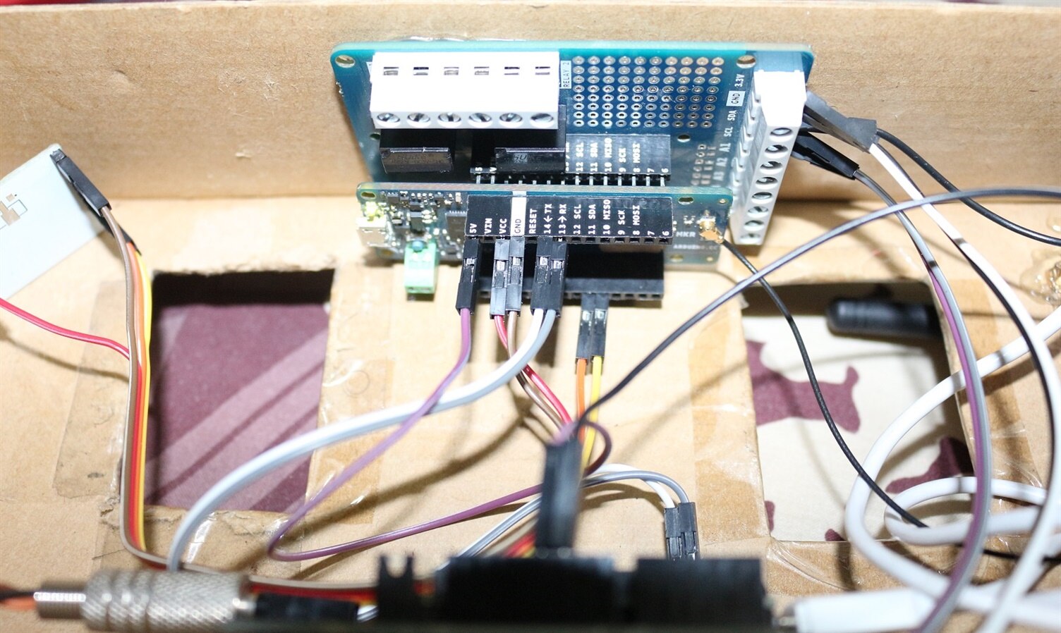
IMAGE TITLE: Complete Base Station Hardware Assembly |
IMAGE TITLE: Arduino MKR WAN 1300 and OLED connections |
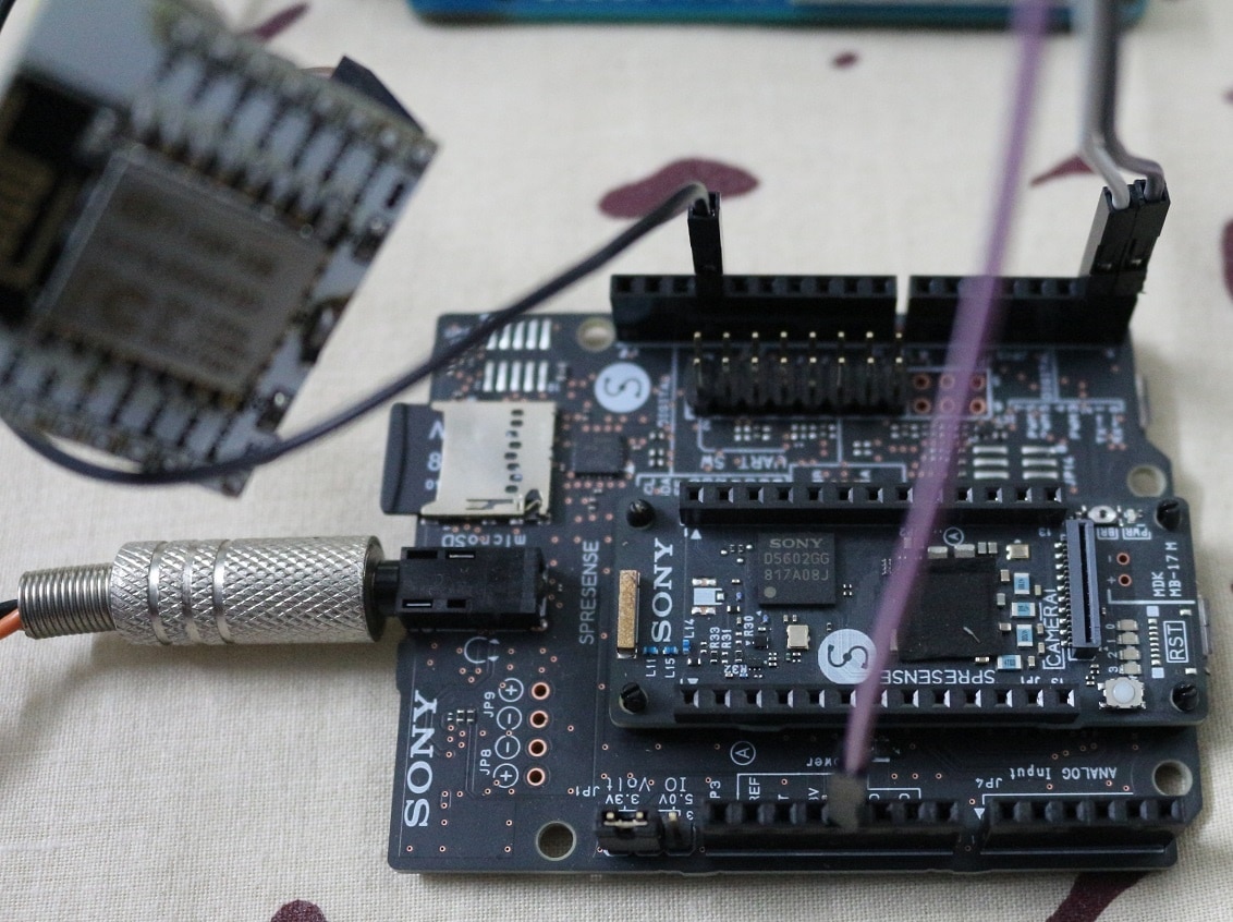
IMAGE TITLE: SONY Spresense connections |
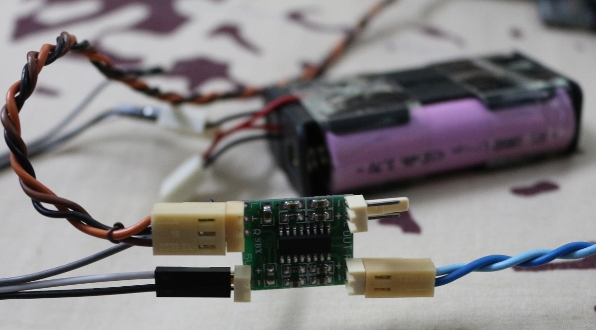
IMAGE TITLE: PAM8403 audio amplifier connections |
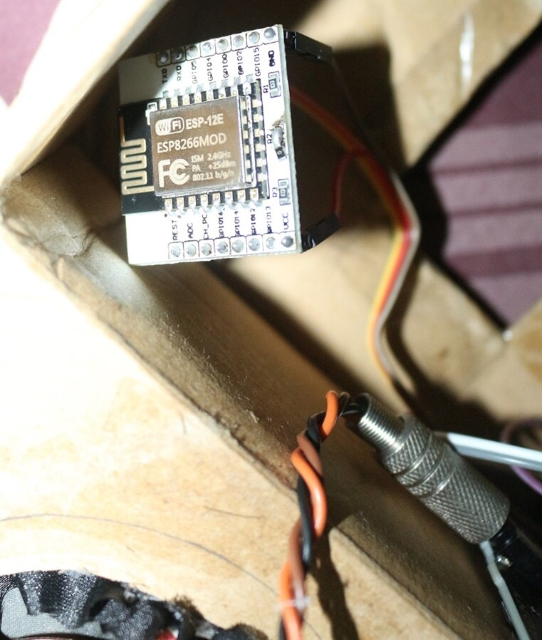
IMAGE TITLE: ESP8266 module connections |
IMAGE TITLE: Arduino MKR WAN 1300 connections |


Software:
All the programming is done using Arduino IDE. The list of all the libraries used in both base station and smart watch is given below;
Libraries:
u8g2 for oled display
RTCZero for Arduino MKR board internal real time clock
Arduino-LORA for p2p communication
WiFilocation for location through wifi scan
AES encryption of data (Not using onboard ECC508 hardware encryption IC with Arduino library: ArduinoECCX08 due to lack of experience with it)
ESPUI for music player GUI and WiFi monitoring
ESPAsyncTCP for web server
ESPAsyncWebServer for web server
NTP for internet time
tinyGPS++ for NEO-6M GPS
and Sony Spresense SDK for audio/music player and offline data logging.
Software Serial alternate for samd21 mcu: SERCOM tutorial from Adafruit and Arduino
There are 2 popular libraries to communicate and display graphics on oled displays based on SSD1306 drivers i) Adafruit SSD1306 ii) U8g2 and I am using later one due to its extensive online help and builtin fonts.
ICON building:
It is easy to communicate certain things through icons instead of text and also you can display lots of info using less space on small displays. Adafruit or u8g2 libraries uses unsigned char [] to display graphics/symbols on oleds which can easily be get from XBM image data. I used following online tools for easy icon building.
- XBM editor
- Or you can simply convert any image to XBM using this online converter

figure 2-7. ICON builder for Oled display (XBM editor with live preview)
Arduino MKR WAN 1300:
Successful GPS initialization and communication with Arduino board at baud rate of 9600. GPS is connected to default Hardware Serial port at pin 13(RX) and 14(TX) of of SAMD21 of Arduino board.
figure 2-8. Successful NEO-6M GPS communication with Arduino MKR WAN 1300 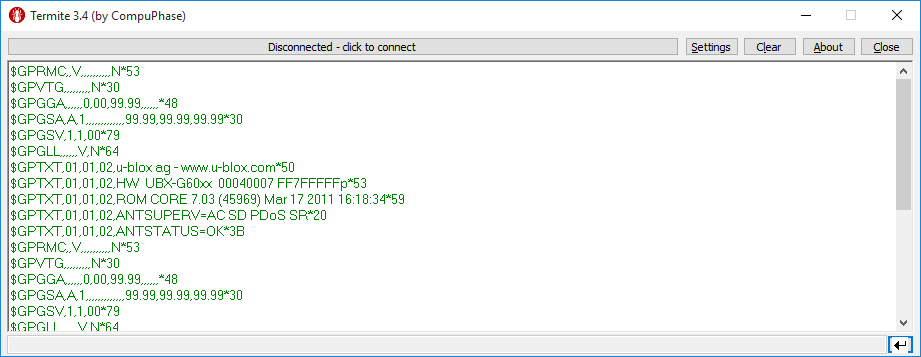
ESP module and GPS both are communicating with SAMD21 of Arduino board through Serial communication but there is only one default serial com port. In order to solve this problem we can add another hardware serial communication interface by taking advantage of various SERCOM interfaces mux with IO pins. You can find all details regarding alternate Serial com interfaces from HERE and variants.cpp file of Arduino MKRWAN1300. Serial1 at SERCOM5 is default hardware serial interface name (figure 2-9) while Serial2 at SERCOM4 is name of serial interface with murata LORA module (figure2-10). Here I am using alternate function of Digital IO pins '0' and '1' at SERCOM3 (figure 2-11).

figure 2-9. Default SAMD21 Hardware Serial communication (SERCOM5) port of Arduino MKR WAN 1300
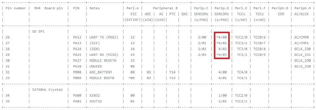
figure 2-10. Default SAMD21 Hardware Serial communication (SERCOM4) port with LORA module of Arduino MKR WAN 1300
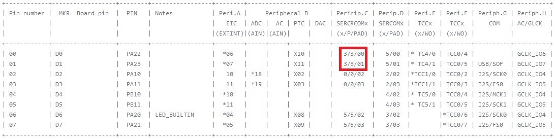
figure 2-11. Alternate function of SAMD21 Digital IOs 0 and 1 (SERCOM3) of Arduino MKR WAN 1300
Add following lines at start of Arduino MKRWAN 1300 code to initialize 2nd Hardware serial at Digital IO pin 0 and 1.
#include "wiring_private.h"

Uart Serial3 (&sercom3, 0, 1, SERCOM_RX_PAD_1, UART_TX_PAD_0); // Create the new UART instance assigning it to pin 0 and 1
void SERCOM3_Handler()
{
  Serial3.IrqHandler();
}
and these two lines inside Arduino void setup() function.
  pinPeripheral(0, PIO_SERCOM); //Assign RX function to pin 0
  pinPeripheral(1, PIO_SERCOM); //Assign TX function to pin 1
Now we can communicate with ESP module and GPS using hardware Serial interfaces. ESP response to WiFi status request should be '3' which is WiFi status code for "WL_CONNECTED". More details about can be found here.
figure 2-9. ESP WiFi status return codes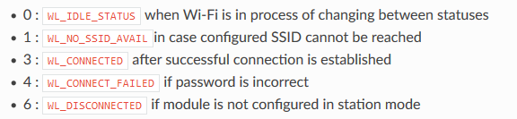
Auto setting of MKR RTC module using NTP Server is easily done by first checking WiFi status and then requesting for NTP server time.
figure 2-10. Debugging MKR board RTC module auto setting using NTP server request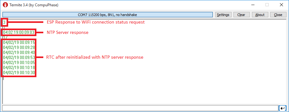
Similarly WiFi Scan command is implemented on ESP8266 module to gather the data of visible WiFi networks for WiFi location finding using Google maps API. ESP module programmed to return only required data. More details about WiFi location using Google maps API can be found here.
figure 2-11. Debugging ESP response to WiFi Scan request
In order to enable SOS and MKR WAN 1300 configuration inputs we need to attach interrupt with each digital input. In this Arduino board not every digital pin can be used as external interrupt input. All the detail about external interrupt enabled detail IO pins can be found HERE and basic info is also shown in figure 2-12. Here I am using A1 and A2 as external interrupt enabled digital inputs and both pins are initialized as INPUT_PULLUP.
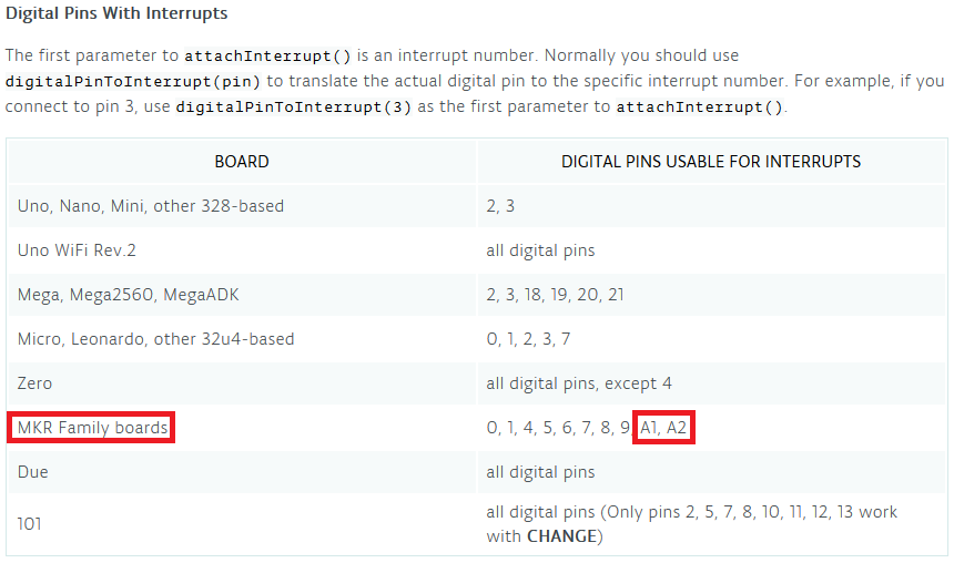 figure 2-11. Arduino MKR WAN 1300 External Digital Interrupt enable pins
During each data transmission through LORAWAN, I am disabling both interrupts to ensure reliable transfer of data and then re-enabled after successful data transmission. SOS feature is only enabled/disabled when both buttons are pressed simultaneously. To add the debouncing effect in ISR of Arduino MKR series we can only use delayMicroseconds() and further details can be found on Arduino attachinterrupt() reference page.
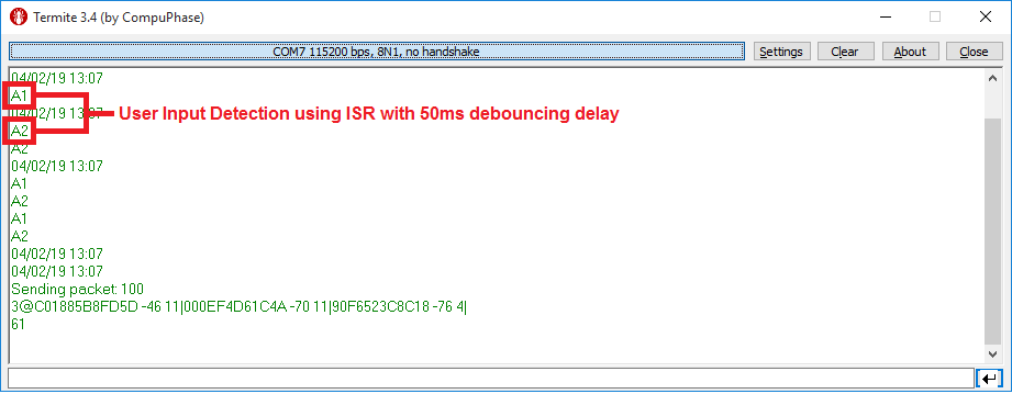
figure 2-11. Arduino MKR WAN 1300 External Digital Interrupt enable pins
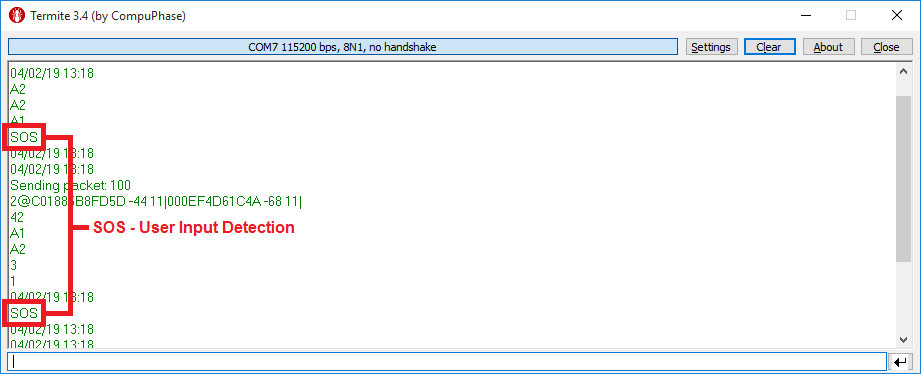
figure 2-12. Arduino MKR WAN 1300 SOS input detection
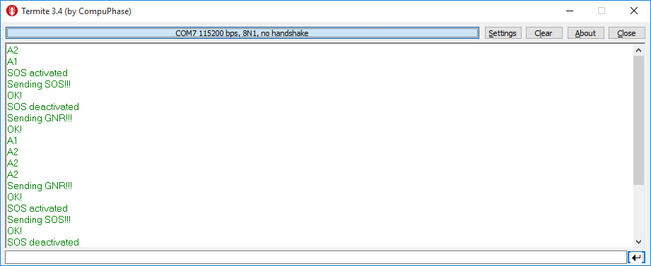
figure 2-13. Operational Verification of SOS feature

figure 2-14. Operational Verification of SOS feature
ESP:
WiFi Module is configured to process commands given by Arduino MKR WAN 1300 board and return the resultant data.
| // | 1 - wifi setup |
| // | 2 - wifi status |
| // | 3 - wifi scan |
| // | 4 - ntp time |
These are the commands implemented in ESP code given below.
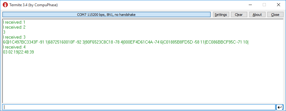
figure 2-15. ESP8266 operational verification for smart watch
ESP8266 is used to format the NTP server response into easily manageable date and time format. Above shown format can be directly used for configuration of RTC module of SAMD21 mcu of Arduino board. Below is list of other possible formatting of time and date using NTP library.
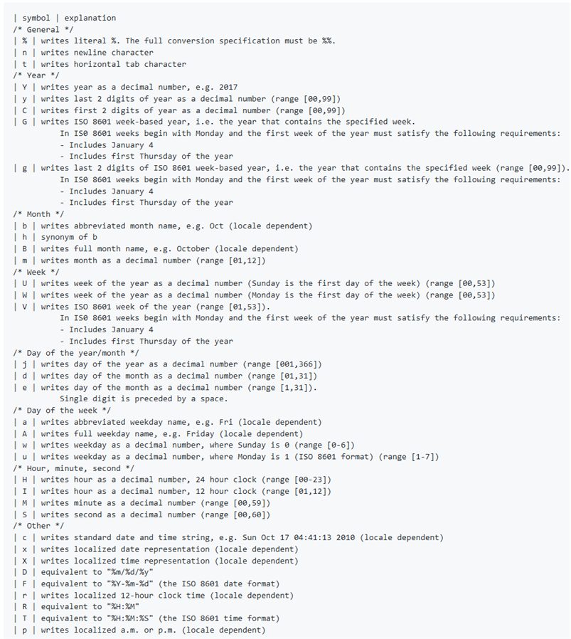
figure 2-16. ESP8266 NTP server easy date and time format symbols with explanation
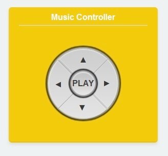
figure 2-17. ESP8266 Web Server with WiFi Music Control
| {gallery} Complete Hardware Testing |
|---|
IMAGE TITLE: tinyMonster - Kids tracker - End Node initialization |
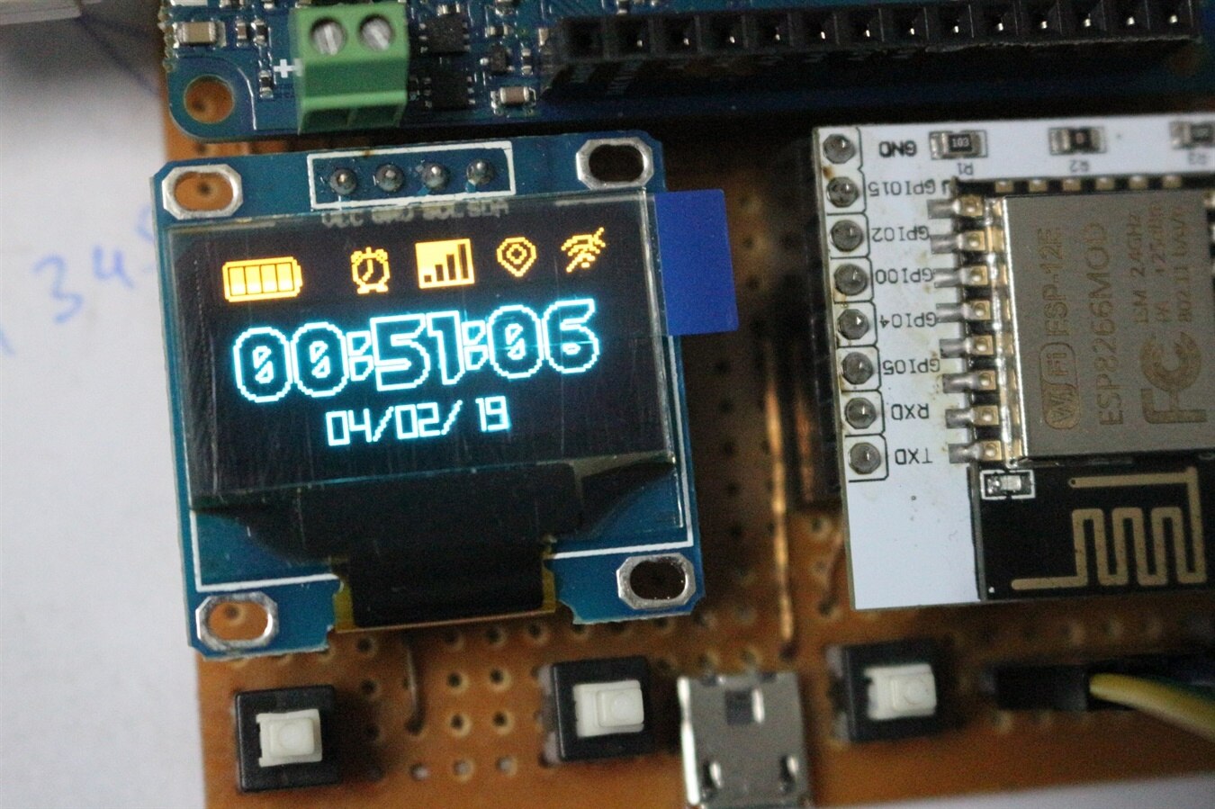
IMAGE TITLE: tinyMonster - Kids tracker - End Node RTC After Auto Setting |
Sony Spresense:
MP3 decoder required to Play audio or music files, can be downloaded from here. After downloading MP3dec make a new directory named "BIN" into home directory of micro sd card and place it inside "BIN" folder. Now MP3DEC file location will be X:\BIN\MP3DEC.

figure 2-18. ESP8266 Web Server commands to Sony Spresense board
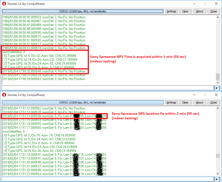
figure 2-19. Indoor testing of Sony Spresense builtin GPS
GPS, Mass storage, Sound Generation and Audio player is implemented by combining SONY SDK examples using Arduino IDE.
Final Enclosures and Demo:
| {gallery} tinyMonster - Smart Watch |
|---|
IMAGE TITLE: Hand made DIY box for Smart Watch |
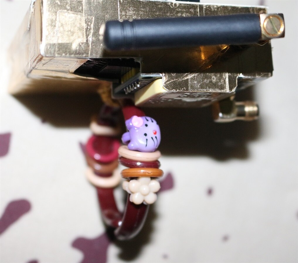
IMAGE TITLE: Kids favorite Hello Kitty Bangle to convert it into wearable device |
IMAGE TITLE: Kids favorite Hello Kitty Bangle to convert it into wearable device |
IMAGE TITLE: Kids favorite Hello Kitty Bangle to convert it into wearable device |
IMAGE TITLE: Kids favorite Hello Kitty Bangle to convert it into wearable device |
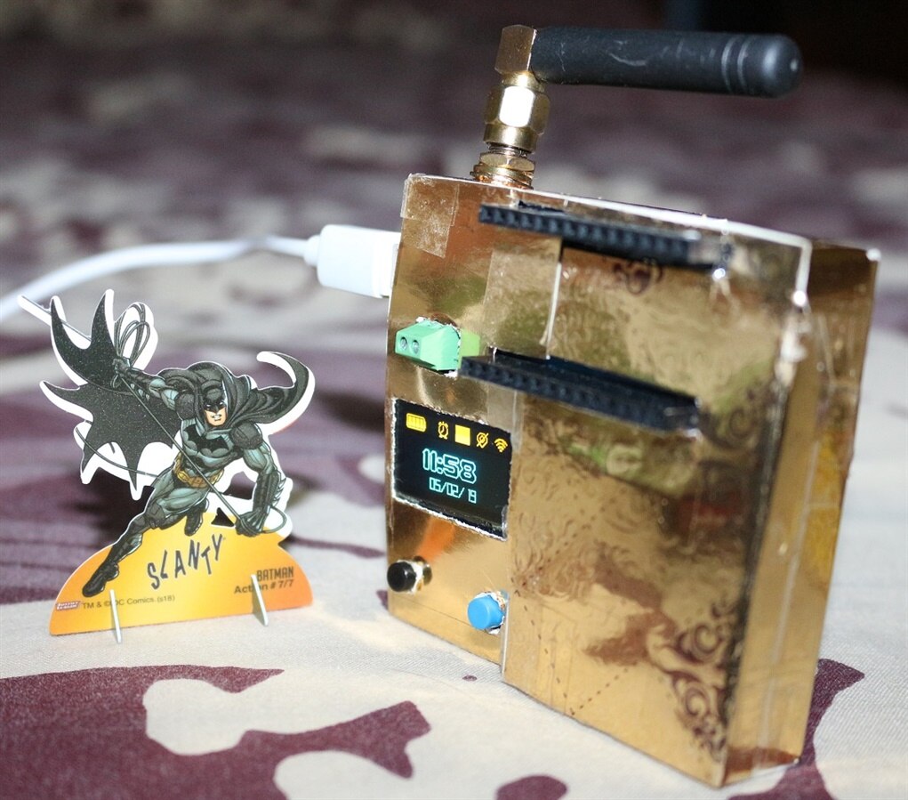
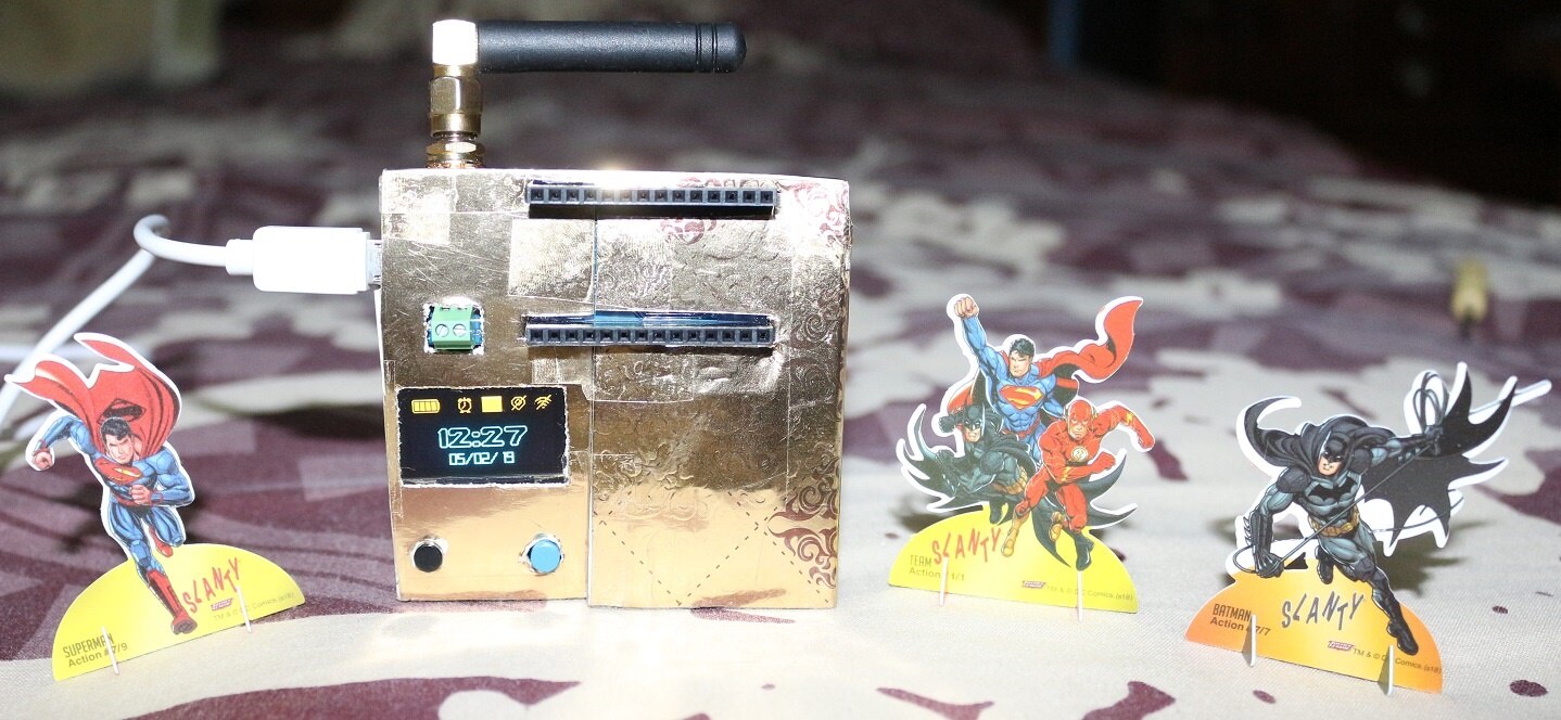
IMAGE TITLE: tinyMonster Smart Watch in action with another Kids favorite super hero "BATMAN" |
IMAGE TITLE: tinyMonster Smart Watch in action with Kids favorite super heroes "SUPERMAN", "BATMAN" and "FLASH" |
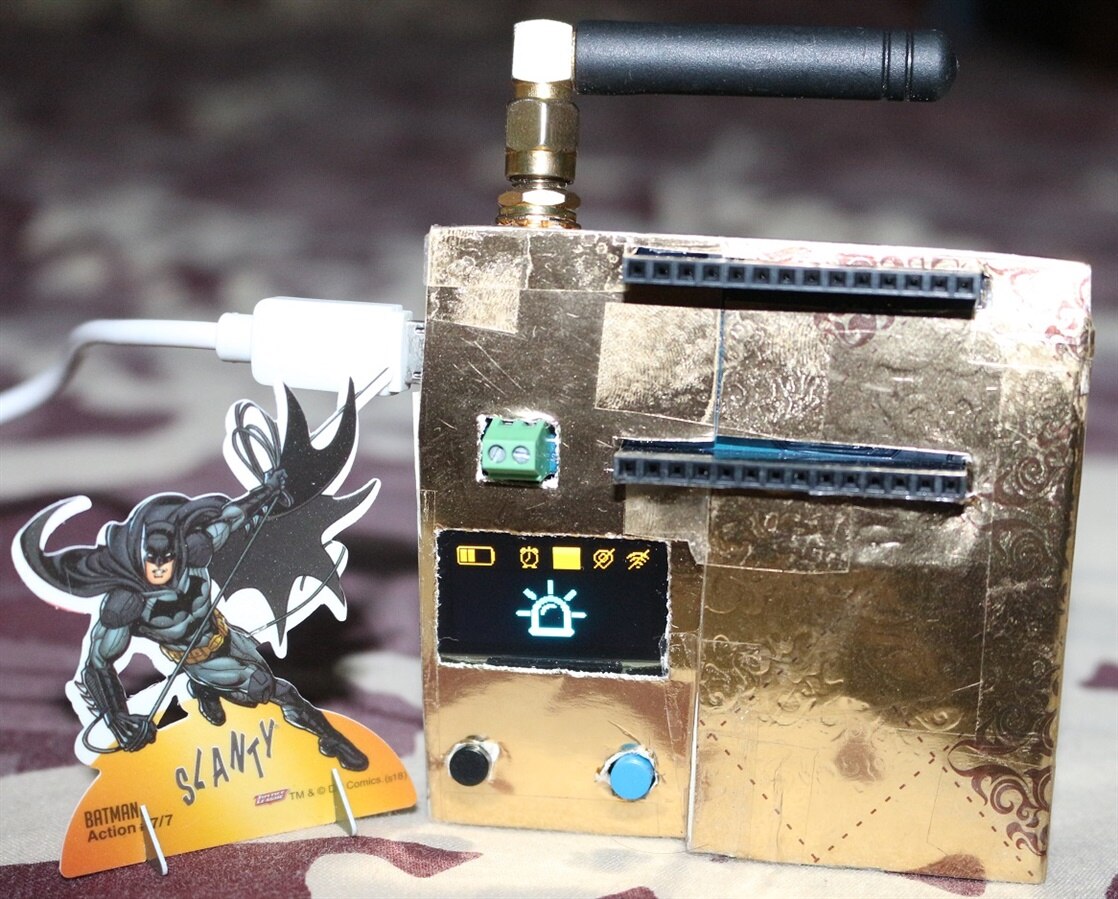
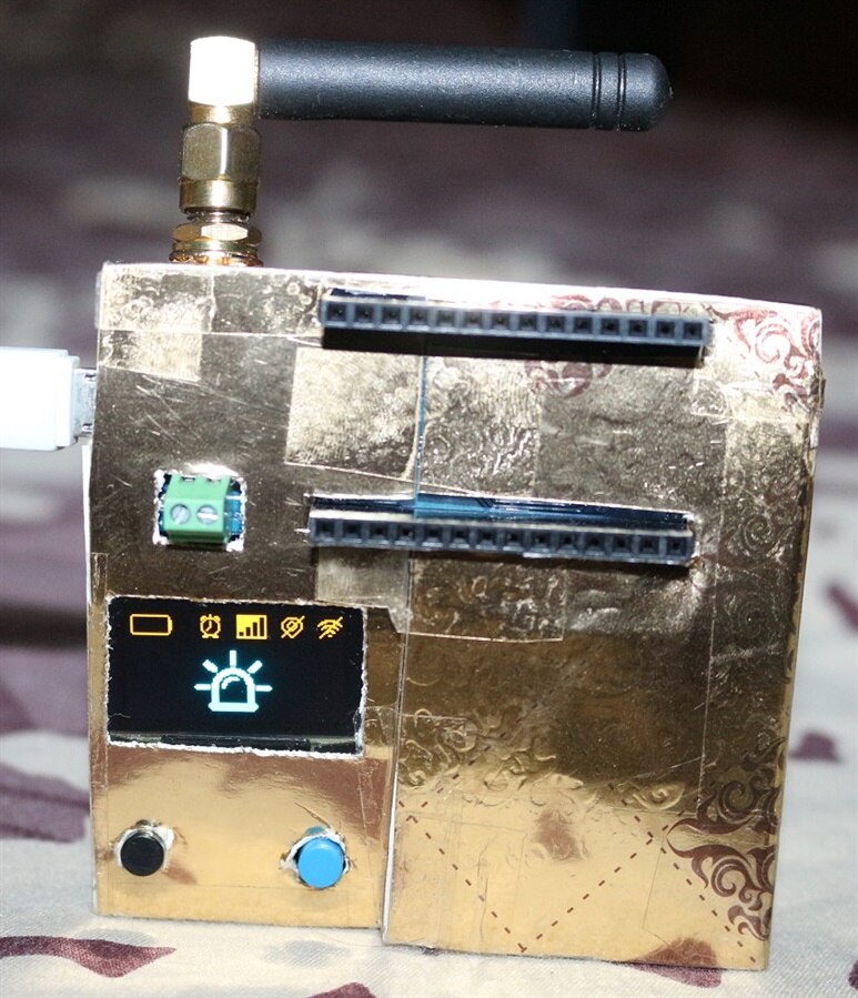
IMAGE TITLE: tinyMonster Smart Watch - SOS request sent and Kids favorite super hero "BATMAN" is coming to rescue you |
IMAGE TITLE: tinyMonster Smart Watch - SOS mode enabled |
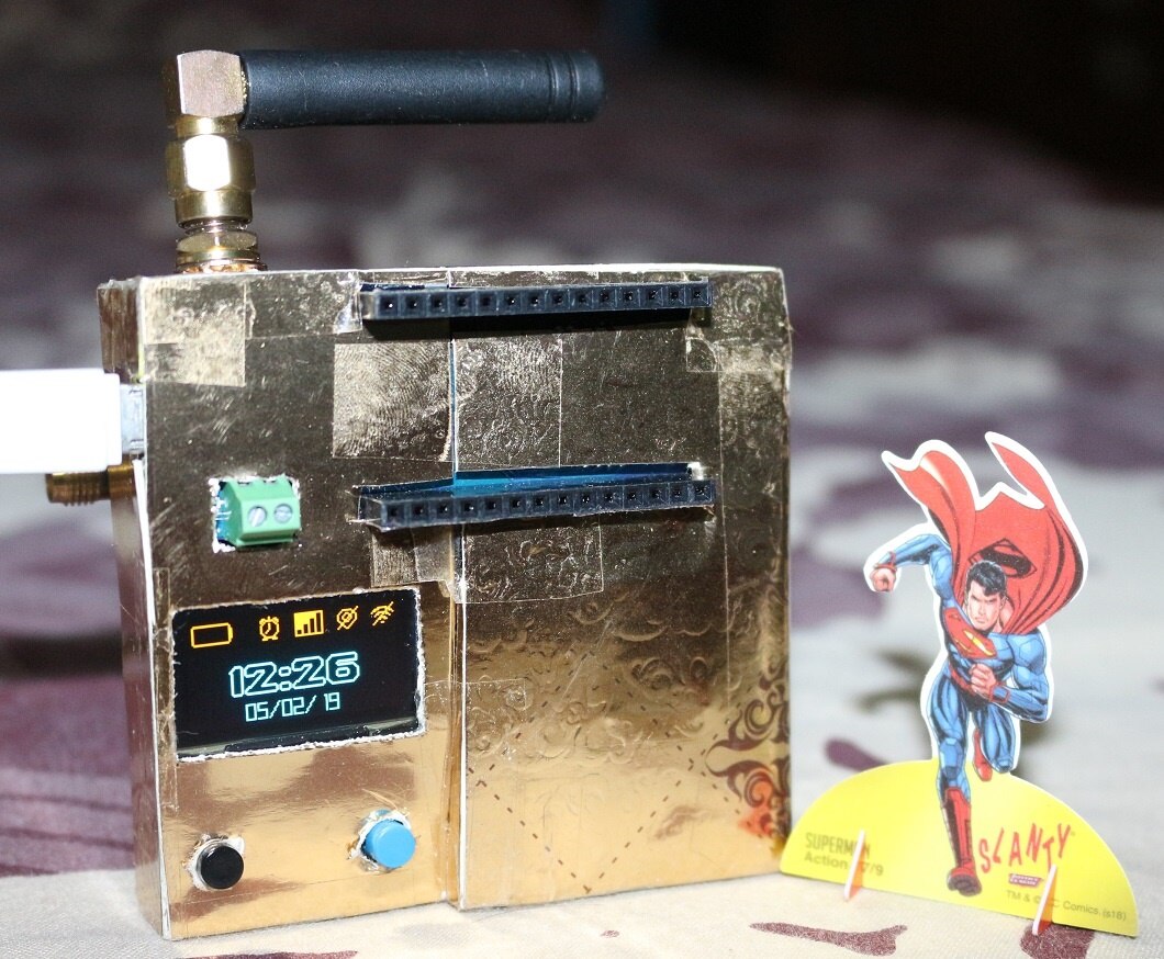
IMAGE TITLE: tinyMonster Smart Watch - Check date and time with everyone's favorite super hero "SUPERMAN" |


.
| {gallery} Base Station with Music Player |
|---|
IMAGE TITLE: |
IMAGE TITLE: Base Station - Arduino MKR WAN 1300 Auto RTC settings with NTP server |
IMAGE TITLE: Base Station - ESP based WiFi RT tracker server and Music Player Control |
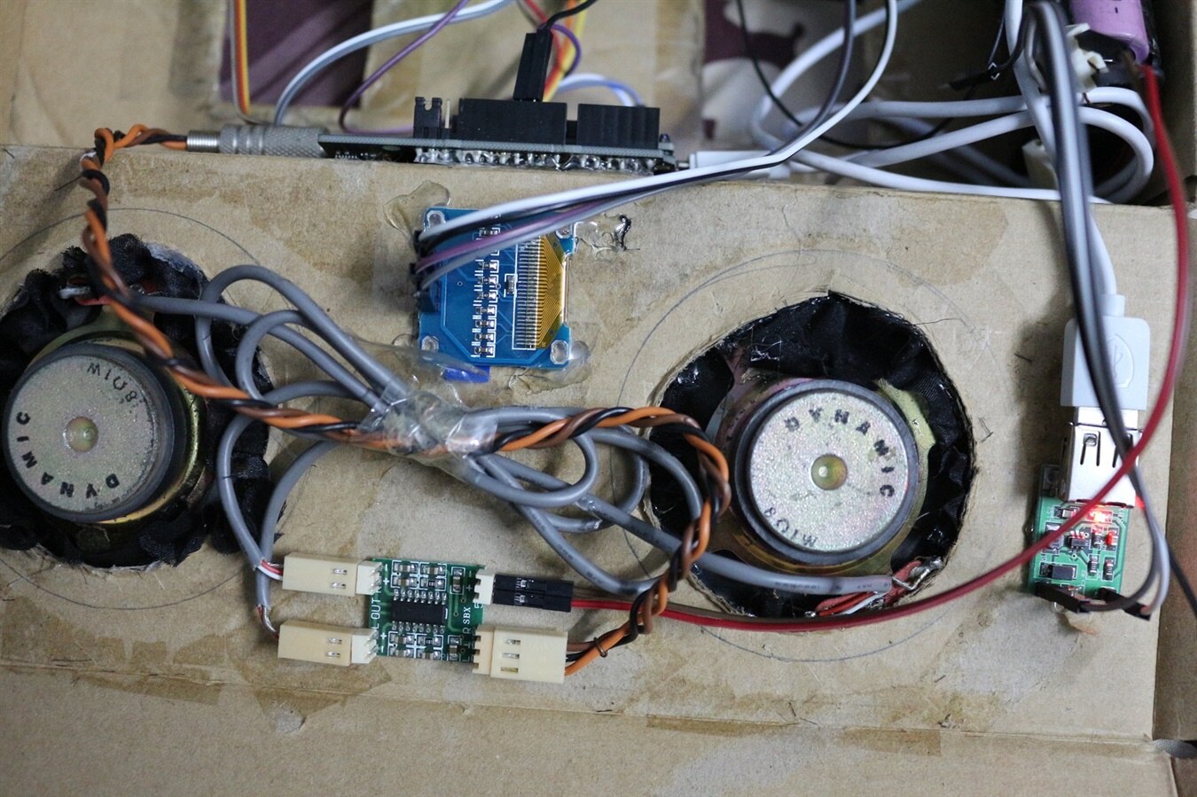
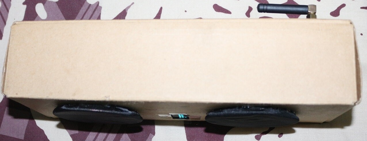
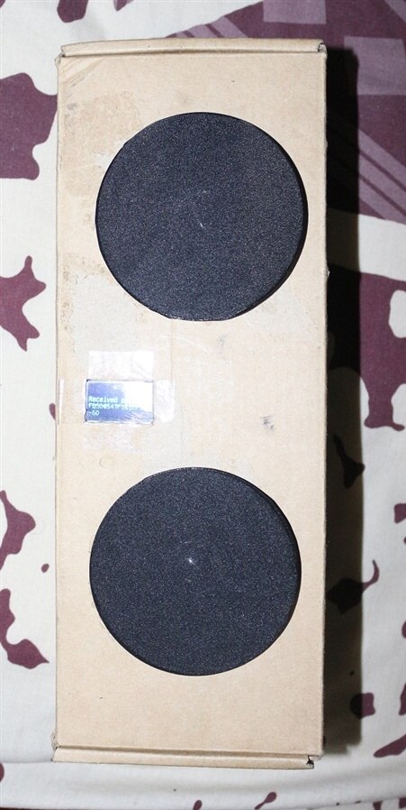
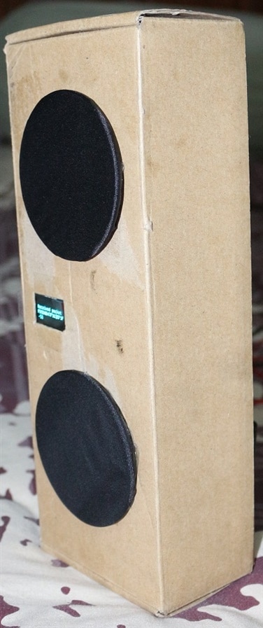
IMAGE TITLE: Base Station - PAM8403 Amplifier Board + 0.96 inch OLED + 5V supply for MCU boards + Stereo Speakers |
IMAGE TITLE: Base Station - 2 Cell Li-Ion Power supply |
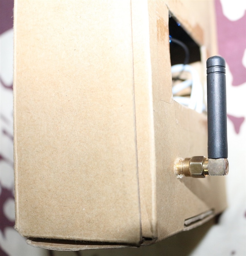
IMAGE TITLE: Base Station - LORA module antenna |
IMAGE TITLE: Base Station - Complete Assembly |
IMAGE TITLE: Base Station - Complete Assembly |
IMAGE TITLE: Base Station - Complete Assembly |


.
Future Work:
There are lots of thing that can be improved in it but here is the list few most important upgrades;
- Using antennas with high gains to increase range
- Add AES or any other encryption to LORA data
- Using different GPS module with higher sensitivity and accuracy
- Adding a touch screen for base station configuration
- Integration of IMU for free fall detection
- Adding a Fuel Gauge for battery charge/discharge monitoring
- Designing a custom PCB instead of veroboard.
- Designing a robust and attractive casing.
- Replacing Serial communication between Arduino MKR WAN 1300 and ESP8266/Spresense with I2C.
- Power consumption optimization
Conclusions:
In this project programming of WiFi module was the easiest part for me. The accuracy of NEO-6M GPS was very poor especially indoor but the builtin GPS of SONY Spresense board was exceptional during indoor and outdoor testing. GPS of Spresense always took less than a min for acquiring time and maximum of 2 min for position lock during indoor testing with onboard small chip antenna. However I am feeling happy with my efforts and progress at the moment. All the communication between each MCU is working perfectly and each radio message between END node and Base station is being received without any problem. The biggest disappointment was the range of LORA module during p2p communication and indoor use. The maximum range that I was able to achieve with indoor base station and outdoor end node is about 150 meters. This can only be increased by reducing the data rate and using very high gain outdoor active antennas for base station. But I am satisfied about the working of the device with automatic RTC setting through GPS/NTP server and mass storage functionality of spresense board for easy data retrieval and addition of new music.
Top Comments