


The Concept
When I saw the Make a Connection theme, I noticed many projects were utilizing Wi-Fi, Bluetooth, and IoT clouds. As an electrical engineering student currently exploring different domains of the field, I’ve recently found myself fascinated by RF engineering. I wanted to take a step back from the software stack and explore the very physical, raw layer of how a connection is actually forged across the airwaves.
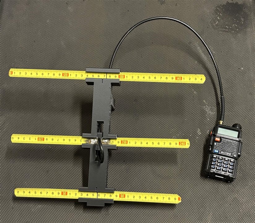
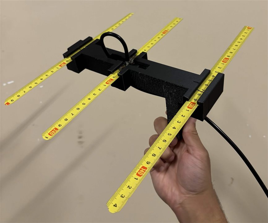
My project is a scratch-built, highly directional 3-element Yagi-Uda antenna tuned for the 70cm amateur radio band (446.000 MHz).
The Application: Fox Hunting
I’ve been looking for practical, hands-on ways to apply RF theory, and one of the coolest aspects of amateur radio is Amateur Radio Direction Finding (ARDF), more commonly known as fox hunting. It’s a game of hide-and-seek with radio waves, where you use directional antennas to physically track down a hidden transmitter.
I wanted to build my own directional antenna for this, but I set a few strict design constraints as a personal engineering challenge:
- It had to be accessible.
- It had to be portable.
- It had to be durable.
- It had to be affordable.
Mechanical Design & 3D Printing
To solve the durability and cost issues, I used standard 16mm steel tape measure blades for the RF elements. Tape measure steel has a brilliant mechanical advantage: it holds its shape perfectly to direct the RF signal, but if it hits an obstacle or gets dropped, it safely folds and instantly snaps back into place without permanent damage.
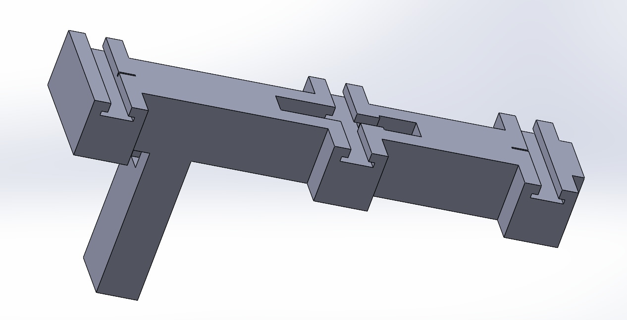
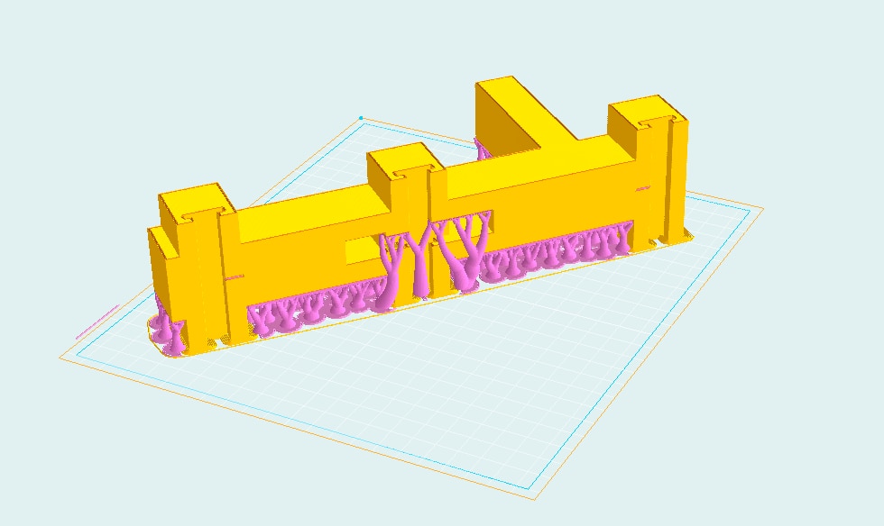
To mount the elements, I opened up SolidWorks and designed a custom, completely fastener-free frame printed in PLA. The entire frame is designed around friction-fit slots. This allows the antenna to be rapidly assembled for a deployment and quickly pulled apart for storage.
Challenge: Friction-Fit Tolerances Getting a friction-fit right in CAD is tricky because every 3D printer extrudes slightly differently. If the slots were too tight, the tape measure wouldn't slide in; if they were too loose, the elements would rattle and ruin the RF coupling. I had to prototype the center block multiple times, tweaking the slot width by fractions of a millimeter to account for the slight curvature of the tape measure blade.
RF Calculations and Spacing
Designing a Yagi requires precise spacing to ensure the elements properly couple and direct the RF energy. I utilized the 3G-Aerial calculator (DL6WU / G3SEK optimization) to determine the exact geometry for 446.000 MHz:
- Active Boom Length: 208 mm
- Reflector to Driven Element Spacing: 116 mm
- Driven Element to Director Spacing: 92 mm
Challenge: Avoiding a Matching Network Many Yagi antennas require a complex matching network (like a Gamma match or a Hairpin match) at the feed point to convert the antenna's natural impedance to 50 ohms. As a student without immediate access to a Vector Network Analyzer (VNA) at home, tuning a Gamma match would have been a nightmare. Instead, I carefully chose element lengths and spacing that naturally resulted in a feed point impedance of ~50 Ohms. This allowed me to directly connect a 50-ohm RG-58 coaxial cable without any extra matching hardware.
Instead of relying on a ruler during assembly, I baked the exact 116 mm and 92 mm dimensions directly into the 3D-printed CAD geometry. You simply mark the center of the cut tape measure blades and slide them into the slots until they align with the center-marks on the print. It bridges the gap between RF calculations and foolproof mechanical assembly.
Challenge: Soldering to Steel Tape
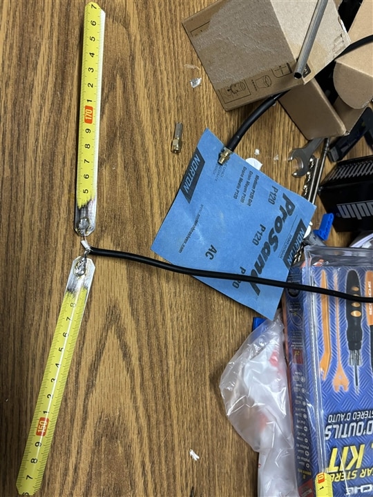
Another physical hurdle in the build was creating a reliable electrical connection between the copper RG-58 coaxial cable and the steel driven elements. Tape measures are coated in paint and a durable clear coat, which completely rejects standard rosin-core solder.
The Solution:
- Mounted the two driven element halves into the printed frame with a precise 8 mm air gap in the center.
- Used sandpaper to aggressively strip the inner edges down to the bare steel.
- Soldered the coax center conductor to one side of the 8mm gap, and the twisted copper shield pigtail to the other.
Field Testing
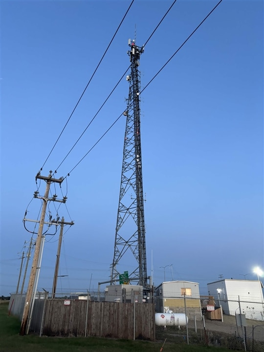
I took the completed build out to the field and connected it to my handheld transceiver (Baofeng UV-5R). Tested on a high power setting, the directional gain (estimated at ~7.3 dBi) makes a considerable difference in establishing a clear line-of-sight simplex connection compared to a standard omnidirectional rubber duck antenna.
It was incredibly rewarding to see the math from a calculator turned into CAD, printed in plastic, and successfully firing RF energy downrange.
Source Files and Conclusion
I wanted this to be as accessible as possible so other students or amateur radio operators can easily build their own. The complete Bill of Materials, SolidWorks source files (so you can adapt it for different tape measure widths), ready-to-print STLs, and assembly documentation are fully open-source.
I highly encourage you to explore the design, adapt the CAD for different tape measure widths, and try building one yourself. You can view the full repository here: https://github.com/shreaypatel/446MHz-Tape-Measure-Yagi
If you have any questions about the build, suggestions, or just want to chat about hardware design and RF, please feel free to drop a comment below or reach out!
Thanks you for reading!
Top Comments