


Alarm with ZIHATEC AZ-Touch, ESP8266 and ESP-NOW communication
In this project we are going to develop an alarm that detects when a door is opened and the presence of a person or animal in a room due to movement. For its realization we have the AZ-Touch kit with 2.8-inch TFT touch screen, linear magnetic hall sensor, passive motion sensor (commonly called PIR sensor) and 3 microcontrollers ESP8266, for communication between the microcontrollers we will use the ESP-NOW communications protocol, which avoids using wiring between the modules.
The ESP-NOW protocol is very versatile, we can use it to communicate several transmitter modules to a single receiver module (the one we are going to use in this project), communicate a transmitter module with several receiver modules and a transmitter to a receiver both in a single direction and bidirectionally and we can also know if the information we have sent has reached the destination. Let's get started.
The materials needed will be:
1 AZ-Touch Mod wall housing set with 2.8 inch touchscreen for ESP8266 and ESP32
1 D1 Mini NodeMcu mit ESP8266-12F WLAN
2 NodeMCU Lua Lolin V3 Module ESP8266 ESP-12F WIFI Wifi Development Board with CH340
1 KY-024 Linear Magnetic Hall Sensor
1 Motion Sensor Motion Detection Module HC-SR501 PIR
Jumper Wire Kabel 40 pc. 20 cm F2F female to female
Batteries
Small magnet
The software needed is:
Arduino IDE
ESP8266WiFi.h library(is part of the ESP8266 definition that we downloaded with the board manager)
espnow.h library (is part of the ESP8266 definition that we downloaded with the board manager).
SPI.h library (integrated)
Adafruit_GFX_h library
Adafruit_ILI9341.h library
XPT2046_Touchscreen.h library
az_touch_receiver_esp8266.ino sketch
hall_sensor_module_1.ino sketch
pir_sensor_module_2.ino sketch
get_mac_address.ino sketch
Fonts/FreeSans9pt7b.h library (is part of the Adafruit_GFX.h library)
Electronic circuit
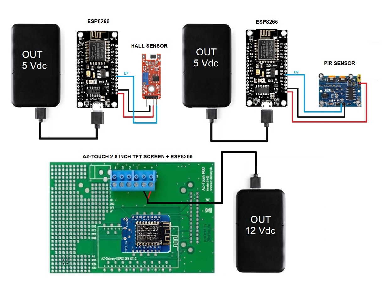
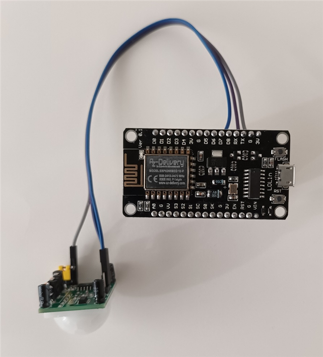
If we analyze the component schematic, we see that we will use two sets of NodeMCU Lolin ESP8266 microcontroller and sensors as emitters and the D1 Mini NodeMCU microcontroller ESP8266 together with the ZIHATEC AZ-Touch kit will be the receiver. The transmitter modules are powered through the micro usb port.
Project and sketchs performance description
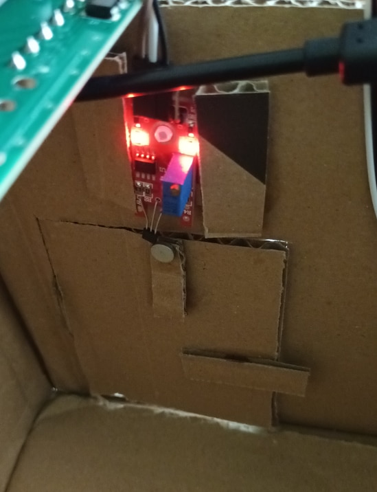
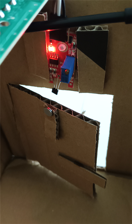
The operation of this project is as follows, the two ESP82266 of the sensors send the information with the data of the number assigned to their sensor and the status (high or low) of the digital pin. The linear magnetic hall sensor will be installed in the upper frame of a door and on the door we will stick a small magnet that is as close as possible to the sensor, the sensor will be at high level with the door closed, since the magnet will be close to the sensor so the situation will be normal and the OK message will appear on the TFT screen next to the name of the sensor, when the door is opened, the small magnet will be removed from the sensor and it will go to low level, then it will change the message on the TFT screen to Alarm and a warning line will appear with the message Door Alarm Detected. The presence sensor (PIR) will be placed in an upper corner of any room, it is at low level as long as it does not detect anything, so the OK message will appear until it detects some presence, go to high level and the Alarm message will appear on the TFT screen, as in the other sensor, a line will appear informing us of PIR Alarm Detected. In both cases when it changes to Alarm, the buzzer will sound until we press on the screen in the Delete message area. In the AZ-Touch kit we have installed the D1 Mini NodeMcu microcontroller that will receive the sensor id data and the status of the digital pin and will manage the display of the messages on the TFT screen and the buzzer sound.
In order to have communication between the microcontrollers ESP8266 we will need the MAC address of the microcontroller that we will use as a receiver, to obtain this address we will connect the microcontroller to the Arduino IDE, select the port to which it is connected, open the Serial Monitor and execute the sketch get_mac_address.ino, the MAC address of the microcontroller will appear in the Serial Monitor, we must save this information because we will need it.
/*-- Sketch to Obtain MAC address ESP module --*/

#ifdef ESP32
#include <WiFi.h>

#else
#include <ESP8266WiFi.h>
#endif

void setup(){
      Serial.begin(115200);
      Serial.println();
      Serial.print("ESP Board MAC Address: ");
      Serial.println(WiFi.macAddress());
}

void loop(){

}
The sketch is very simple, first check the ESP32 or ESP8266 microcontroller model and load the appropriate library to know the MAC address.
This alarm project consists of three sketches: hall_sensor_module_1.ino, pir_sensor_module_2.ino and az_touch_receiver_esp8266.ino, the names are quite clarifying and reflect the circuits they belong to. The two sketches of the sensors are practically the same, just change the sensor identification number and add a line with a delay in the sketch of the presence sensor for optimal operation. Let's move on to describing the sketch of the presence sensor and the AZ-Touch module.
Sketch pir_sensor_module_2.ino (presence sensor) description
As we are going to use ESP8266 microcontrollers and the ESP-NOW communication protocol, we must include their libraries to be able to implement their methods and instructions.
#include <ESP8266WiFi.h
#include <espnow.h>
After the libraries, we must define the GPIO pin of the ESP8266 to which we will connect the sensor's digital pin, the connection pin to the ESP8266 is D7 which, consulting the datasheet, corresponds to GPIO 13. In the next line we must reflect the MAC address of the module to which we are going to send the data, this MAC is in this project that of the D1 Mini NodeMCU receiver microcontroller ESP8266 of the AZ-Touch (the reflected address is that of our ESP8266 of the project, the D1 Mini NodeMCU must be written ESP8266 that it is used as a receiver in each case). In the third line we must configure the number with which the sensor will be identified, as you can see, for the PIR sensor it is emiter_board_id 2, while for the linear magnetic hall sensor we have chosen emiter_board_id 1.
int pir_sensor = 13;
uint8_t receiver_board_MAC_address[] = {0xA4, 0xCF, 0x12, 0xF4, 0xCE, 0x12};
#define emiter_board_id 2
Then we must configure the structure that contains the data that we are going to send, we have named it sensor_state and we define the variables that we will use for the project, id will be the sensor number (number 2 for the PIR sensor and number 1 for the linear magnetic hall sensor) and the value variable, which will contain the value of the state of the sensor's digital output.
typedef struct sensor_state {
    int id;
    int value;
} sensor_state;
Once we have the structure defined, we need to implement an object of that structure, as you can see, we have named it state.
sensor_state state
For the cadence of the sensor check time, we have created two variables that will contain the time of the last check performed lastTime and timerDelay which will be the cadence of the sensor check time, in our case it will be every second (1000 usg).
unsigned long lastTime = 0;
unsigned long timerDelay = 1000;
One of the characteristics of the ESP-NOW protocol is that we can obtain information about the status of the data sent, for this we must perform a "callback" with the OnDataSent method that has as arguments *mac_addr which is the MAC address of the receiving microcontroller and sendStatus which is the status of the send, when a 0 is received it will mean that the data send has been successful, while if a 1 is received, it will mean that the data send has failed. The data submission status information is displayed by the Serial Monitor.
void OnDataSent(uint8_t *mac_addr, uint8_t sendStatus) {
        Serial.print("\r\nLast Packet Send Status: ");
        if (sendStatus == 0){
        	Serial.print("Delivery success");
 } else{
              Serial.println("Delivery fail");
 }
}
We implemented the setup() method to set the initial state of the microcontroller when voltage is connected or reset. The first thing we do is initialize the Serial Monitor.
Serial.begin(115200);
The communication between the modules will be done through Wi-Fi, but we will not use the wireless network of the router, so we must disconnect the ESP8266 from the local network with WiFi.disconnect() and configure it as an independent Wi-Fi station .mode(WIFI_STA).
WiFi.mode(WIFI_STA);
WiFi.disconnect();
The next thing we must program is to check if our module has ESP8266 been initialized correctly and inform by the Serial Monitor if this has not happened, we do this with the if conditional.
if (esp_now_init() != 0) {
	Serial.print("Error initializing ESP-NOW");
	Return;
}
Once the ESP8266 has been initialized, as this module is an information emitter, we must configure it as such with the esp_now_set_self_role(ESP_NOW_ROLE_CONTROLLER) statement. In the next line we create the esp_now_register_send_cb record to execute the callback. Then we must create a communication channel with the receiver by adding the receiving ESP8266 to the ESP-NOW communication table through the esp_now_add_peer(receiver_board_MAC_address, ESP_NOW_ROLE_SLAVE, 1, NULL, 0) statement, where the arguments are the MAC address of the receiver module, the following argument must be configured as "slave" being receiver, the next argument is the communication channel, usually from 1 to 13, in this case we choose channel 1, the last two arguments would be the communication key and the length, as we do not configure access key, we write NULL, so the length of this is 0 (the last argument).
esp_now_set_self_role(ESP_NOW_ROLE_CONTROLLER);
esp_now_register_send_cb(OnDataSent);
esp_now_add_peer(receiver_board_MAC_address, ESP_NOW_ROLE_SLAVE, 2, NULL, 0);
The next line is only reflected in the motion sensor sketch, as we must let the sensor stabilize when applying voltage to it so that it performs reliable detection. We set up a 1-minute wait.
delay (60*1000);
With this last line we have finished the setup() method. The loop() method only has a simple conditional block, which should be executed when a second has passed, since it is the cadence we set in the sketch declaration block. To execute the if block we check if 1 second has passed by subtracting the saved time of the last data send (lastTime) with the current time (millis), if a second has passed a data packet is sent with the fields (sensor number and state of the sensor's digital pin) that we define in the sensor_state data structure. The three arguments of the instruction esp_now_send(0, (uint8_t *) &state, sizeof(state)) are the MAC address of the receiving microcontroller, in this case with 0 we send the data to all the addresses in the table (we only have one receiver), the next argument is the packet with the two data we send (id and state of the digital pin) and the last argument is the length of the data packet we send. With the last line, we save the time of the last data send in the lastTime variable.
if ((millis() - lastTime) > timerDelay) {
	state.id = emiter_board_id;
	state.value = digitalRead (pir_sensor);
	esp_now_send(0, (uint8_t *) &state, Sizeof(state));
	lastTime = Millis();
}
hall_sensor_module_1 complete sketch
/*-------------------------------------------------------------------------
   Alarm project with ZIHATEC AZ-Touch 2.8 inch TFT screen with touch screen,
   ESP8266 and ESP-NOW communication protocol.

   The components needed are:
    - ZIHATEC AZ-Touch 2.8 inch
    - PIR sensor
    - Hall sensor
    - NodeMCU Lua Lolin V3 Module ESP8266 ESP-12F WIFI
    - D1 Mini NodeMCU ESP8266

    Miguel Torres Gordo
    Getafe (Madrid) - ESPAÑA          Last revision 02-11-2022

-------------------------------------------------------------------------*/


#include <ESP8266WiFi.h>							      // Library required for the ESP8266
#include <espnow.h>								          // Library required to use the ESP-NOW protocol

int hall_sensor = 13;								        // Connection the data line hall sensor to GPIO's pins ESP8266
uint8_t receiver_board_MAC_address[] = {0xA4, 0xCF, 0x12, 0xF4, 0xCE, 0x12};   // MAC address of my ESP8266 receiver module, you must change to the MAC address of your ESP8266 receiver
#define emiter_board_id 1                   // Set the number board id (in this project the hall sensor is the number 1)

typedef struct sensor_state {               // Structure to send data. Must match the receiver structure
      int id;                               // Hall sensor module identity
      int value;                            // Hall sensor digital signal value
} sensor_state;

sensor_state state;                         // Create a struct_message called test to store variables to be sent

unsigned long lastTime = 0;                 // Variable to store the value of the time of the last check
unsigned long timerDelay = 1000;            // Value of time of last sensor check

/*--  Function called when data has been sent  --*/
void OnDataSent(uint8_t *mac_addr, uint8_t sendStatus) {      // Callback when data is sent
        Serial.print("\r\nLast Packet Send Status: ");        // Message on the Serial Monitor
        if (sendStatus == 0){                                 // Checking the status of information sending
        Serial.println("Delivery success");                   // If the above condition is true, successfully sent information appears in the serial Monitor
        } else{                                               // If it is false, the following line of code is executed
              Serial.println("Delivery fail");                // Message on the serial monitor communicating the failure to send the information
        }
}

/*----  Method setup() for setting the initial conditions  ----*/
void setup() {
        Serial.begin(115200);                                       // Serial Monitor initialization

        WiFi.mode(WIFI_STA);                                        // Configuration of the ESP8266 module as a wifi station
        WiFi.disconnect();                                          // Disconnect the ESP8266 module from the router's wifi network

        if (esp_now_init() != 0) {                                  // If the ESP-NOW protocol does not initialize,
                  Serial.println("Error initializing ESP-NOW");     // the information is displayed by the Serial Monitor
                  return;
        }

        esp_now_set_self_role(ESP_NOW_ROLE_CONTROLLER);             // We configure the ESP8266 as a controller, so that it send the information
        esp_now_register_send_cb(OnDataSent);                       // Once ESP-NOW is successfully init, we will register for Send CB to get the status of Trasnmitted packet
        esp_now_add_peer(receiver_board_MAC_address, ESP_NOW_ROLE_SLAVE, 1, NULL, 0);      // esp_now_add_peer() pairs the slave ESP8266 with the ESP8266 of the hall sensor
                                                                                           // module to send data to the slave ESP8266
}

/*----  Method loop()  ----*/
void loop() {
        /*---  Check of the time elapsed since the last information was sent,  ----*/
        /*---  if it is greater than the time set in timerDelay, the conditional block is executed  ---*/
        if ((millis() - lastTime) > timerDelay) {                           // Check of the time elapsed
                  state.id = emiter_board_id;                               // Set Hall sensor module identification value
                  state.value = digitalRead (hall_sensor);                  // Setting the digital signal value of the Hall sensor module
                  esp_now_send(0, (uint8_t *) &state, sizeof(state));       // Send message via ESP-NOW
                  lastTime = millis();                                      // Store the value of the current time in the variable lastTime
  }
}
pir_sensor_module_2 complete sketch
/*-------------------------------------------------------------------------
   Alarm project with ZIHATEC AZ-Touch 2.8 inch TFT screen with touch screen,
   ESP8266 and ESP-NOW communication protocol.

   The components needed are:
    - ZIHATEC AZ-Touch 2.8 inch
    - PIR sensor
    - Hall sensor
    - NodeMCU Lua Lolin V3 Module ESP8266 ESP-12F WIFI
    - D1 Mini NodeMCU ESP8266

    Miguel Torres Gordo
    Getafe (Madrid) - ESPAÑA          Last revision 02-11-2022

-------------------------------------------------------------------------*/


#include <ESP8266WiFi.h>                    // Library required for the ESP8266
#include <espnow.h>                         // Library required to use the ESP-NOW protocol

int pir_sensor = 13;                        // Connection the data line PIR sensor to GPIO's pins ESP8266
uint8_t receiver_board_MAC_address[] = {0xA4, 0xCF, 0x12, 0xF4, 0xCE, 0x12};   // MAC address of my ESP8266 receiver module, you must change to the MAC address of your ESP8266 receiver
#define emiter_board_id 2                   // Set the number board id (in this project the PIR sensor is the number 2)

typedef struct sensor_state {               // Structure to send data. Must match the receiver structure
    int id;                                 // PIR sensor module identity
    int value;                              // PIR sensor digital signal value
} sensor_state;

sensor_state state;                         // Create a struct_message called test to store variables to be sent

unsigned long lastTime = 0;                 // Variable to store the value of the time of the last check
unsigned long timerDelay = 1000;            // Value of time of last sensor check

/*--  Function called when data has been sent  --*/
void OnDataSent(uint8_t *mac_addr, uint8_t sendStatus) {      // Callback when data is sent
        Serial.print("\r\nLast Packet Send Status: ");        // Message on the Serial Monitor
        if (sendStatus == 0){                                 // Checking the status of information sending
        Serial.println("Delivery success");                   // If the above condition is true, successfully sent information appears in the serial Monitor
        } else{                                               // If it is false, the following line of code is executed
              Serial.println("Delivery fail");                // Message on the serial monitor communicating the failure to send the information
        }
}

/*----  Method setup() for setting the initial conditions  ----*/
void setup() {
        Serial.begin(115200);                                       // Serial Monitor initialization

        WiFi.mode(WIFI_STA);                                        // Configuration of the ESP8266 module as a wifi station
        WiFi.disconnect();                                          // Disconnect the ESP8266 module from the router's wifi network

        if (esp_now_init() != 0) {                                  // If the ESP-NOW protocol does not initialize,
                  Serial.println("Error initializing ESP-NOW");     // the information is displayed by the Serial Monitor
                  return;
        }

        esp_now_set_self_role(ESP_NOW_ROLE_CONTROLLER);             // We configure the ESP8266 as a controller, so that it send the information
        esp_now_register_send_cb(OnDataSent);                       // Once ESP-NOW is successfully init, we will register for Send CB to get the status of Trasnmitted packet
        esp_now_add_peer(receiver_board_MAC_address, ESP_NOW_ROLE_SLAVE, 1, NULL, 0);       // esp_now_add_peer() pairs the slave ESP8266 with the ESP8266 of the PIR sensor
                                                                                            // module to send data to the slave ESP8266
        delay (60*1000);                    // This wait is necessary for the PIR sensor detection to be stable
}

/*----  Method loop()  ----*/
void loop() {
        /*---  Check of the time elapsed since the last information was sent,  ----*/
        /*---  if it is greater than the time set in timerDelay, the conditional block is executed  ---*/
        if ((millis() - lastTime) > timerDelay) {                           // Check of the time elapsed
                  state.id = emiter_board_id;                               // Set PIR sensor module identification value
                  state.value = digitalRead (pir_sensor);                   // Setting the digital signal value of the Hall sensor module
                  esp_now_send(0, (uint8_t *) &state, sizeof(state));       // Send message with the data via ESP-NOW
                  lastTime = millis();                                      // Store the value of the current time in the variable lastTime
  }
}
Sketch az_touch_receiver_esp8266 description
This sketch will be loaded into the D1 Mini NodeMCU microcontroller ESP8266 which will be installed on the ZIHATEC AZ-Touch and will be the receiver of the data. The first two libraries that we must include are those necessary to use our ESP8266 and the ESP-NOW communication protocol.
#include <ESP8266WiFi.h>
#include <espnow.h>
The following libraries that we must include are those necessary to be able to use the functions of Arduino (Arduino.h), the SPI communication protocol (SPI.h) to be able to communicate with the TFT screen, we must also load the libraries to use said TFT screen (Adafruit_ILI9341.h), to use the instructions of graphic functions (Adafruit_GFX.h) and use the "touchscreen" (XPT2046_Touchscreen.h). The last library (Fonts/FreeSans9pt7B.h) that we include is the one that contains the bitmap of the fonts or letters.
#include <Arduino.h>
#include <SPI.h>
#include "Adafruit_GFX.h"
#include "Adafruit_ILI9341.h"
#include <XPT2046_Touchscreen.h>
#include <Fonts/FreeSans9pt7b.h>
The next line is just a comment that we're going to use the 2.8-inch screen on the ZIHATEC AZ-Touch.
#define AZ_TOUCH_MOD_BIG_TFT
We should configure the pins to which the TFT display will be connected, but these are already configured by default by the design of the ZIHATEC AZ-Touch, in the statement we indicate the GPIO port to which they are connected. The first line is only an indication that the display has the yellow pin connector. The second statement (#define TFT_CS 5) is the connection to the GPIO pin to enable or disable the TFT display, the third statement (#define TFT_DC 4) is the connection to the GPIO pin to which the TFT display Data-Command pin is connected that is used to tell you whether it receives data or a command, and the last statement (#define TFT_LED 15) is the connection to the GPIO pin to turn the TFT display on or off. Screen backlight.
Now we are going to declare the pins to which the "touchscreen" of the TFT screen will be connected, just like on the screen, these pins are also defined by the design of the ZIHATEC AZ-Touch, we also indicate the GPIO port to which they are connected. The first line is only an indication that the screen has a touchscreen. The second statement (#define TOUCH_CS 0) is the connection to the GPIO pin to enable or disable the touchscreen, and the third statement (#define TOUCH_IRQ 4) is the connection to the GPIO pin to indicate that the touchscreen has been touched.
#define HAVE_TOUCHPAD
#define TOUCH_CS 0
#define TOUCH_IRQ 2
As we have a small buzzer, we will enable it by connecting it to the GPIO 16 pin of our D1 Mini NodeMCU ESP8266, we declare it as follows:
#define buzzer 16
The next thing we configure in the declaration block in this sketch will be the parameters to use the "touchscreen", in order to interact with it we need a minimum pressure on the screen, we configure it with #define MINPRESSURE 10 and we also need to configure the limits of the X and Y axes to be able to interact, we reflect the values of the analog to digital conversion for the minimum and maximum values of the X and Y coordinates of the screen.
#define MINPRESSURE 10
#define TS_MINX 370
#define TS_MINY 470
#define TS_MAXX 3700
#define TS_MAXY 3600
In order to use the methods and instructions of both the screen and the touchscreen, we must implement an object from each library and as arguments we must reflect the CS pin and also, for the screen we must indicate the DC pin. The functions of each pin have already been explained above.
Adafruit_ILI9341 tft_screen = Adafruit_ILI9341(TFT_CS, TFT_DC);
XPT2046_Touchscreen touch_screen(TOUCH_CS);
Now we have to configure the structure that receives the data that the emitter modules will send, this structure must be the same as the one programmed in the two sketches of the emitter modules. As you may remember, we called it sensor_state and it defined the id variables , which is the sensor number, and the value variable, which will contain the value of the state of the digital pin of each sensor. We will also create the state variable of this structure to contain the received data.
typedef struct sensor_state {
      int id;
      int value;
} sensor_state;

sensor_state state;
Next, we create a variable from the previous structure for each emitter to which the data received from the corresponding emitter module will be assigned, we also create a matrix that will contain these last variables created from the emitter modules.
sensor_state hall_sensor;
sensor_state pir_sensor;

sensor_state emiter_boards[2] = {hall_sensor, pir_sensor};
As programmed in the sketch of the emitter modules, in the receiver module we also make a "callback" that will be executed when the receiver module receives data through ESP-NOW. The void function OnDataRecv accepts several arguments and we have programmed it to show us through the Serial Monitor the MAC address of the sending module with uint8_t * mac_addr, the status data of the digital pin of the sending module with uint8_t *incomingData and the size of the data received with uint8_t len .
In the 18-character char matrix macStr[18] we save the characters received from the MAC address of the modules and with the function snprintf(macStr, sizeof(macStr), "%02x:%02x:%02x:%02x:%02x:%02x", mac_addr[0], mac_addr[1], mac_addr[2], mac_addr[3], mac_addr[4], mac_addr[5]) we assign the characters of the array to the x's of the text string and then represent it by the Serial Monitor with Serial.println(macStr).
void OnDataRecv(uint8_t * mac_addr, uint8_t *incomingData, uint8_t len) {
	char macStr[18];
	Serial.print("Packet received from: ");

	snprintf(macStr, sizeof(macStr), "%02x:%02x:%02x:%02x:%02x:%02x", mac_addr[0], mac_addr[1], mac_addr[2], mac_addr[3], mac_addr[4], mac_addr[5]);

	Serial.println(macStr);
Before continuing with the explanation of the sketch we must remember two things:
- In the corresponding emitter sketches, we assign the linear magnetic hall sensor the emitter module id 1 (#define emiter_board_id 1) and the proximity sensor the emitter module id 2 (#define emiter_board_id 2).
- In the sketch of the receiver module we have created an array with the names of the sensors (sensor_state emiter_boards[2] = {hall_sensor, pir_sensor}), in the arrays, the first element is assigned the id 0 and the second the id 1.
It is necessary to remember this because we are going to use [state.id-1] to know the sensor that has sent the information, so, the ESP8266 of the magnetic hall sensor sends the information with ID 1, so to know the ESP8266 that has sent the information with the data we must subtract 1 from the received ID and check in the matrix the sensor that corresponds to that position.
Continuing with the sketch of the receiver, in the sketch line memcpy(&state, incomingData, sizeof(state)) we copy the content of the data of the variable incomingData into the state variable of the structure with the values that one of the ESP8266 has sent. We identify the sender that has sent the data by [state. id-1] of line emiter_boards, on this same line we also know the state of the digital pin of that module, since the value in [state. id-1].value. By the Serial Monitor we display the digital pin status information with 0 or 1 and the length of the information, usually 8 bytes.
memcpy(&state, incomingData, sizeof(state));
Serial.printf("Sensor %u: %u bytes\n", state.id, len);

emiter_boards[state. id-1].value = state.value;
Serial.printf("state: %d \n", emiter_boards[state. id-1].value);
Serial.println();
To display the information on the TFT screen we must take into account that there is static text (the title, the names of the sensors and the line to delete the messages) and dynamic text (the status of the sensors and the line with the information of the sensor that has detected the intrusion); as the static text does not change, we have programmed it in the setup() method, while for the dynamic one we have programmed it within the OnDataRecv function which is the one that will be continuously executed. We will now describe how dynamic text is displayed.
As the digital pin status of the sensors can be in HIGH or LOW state and we have two sensors, we have programmed a double conditional to first check the received value of the digital pin status and once inside each condition, we have programmed a multiple conditional with SWITCH to know which of the sensors has sent the value.
Then, the first condition is to check that the state of the digital pin of the received data is in HIGH state (if(state.value == HIGH)), if this condition is met, the instructions of the if block are executed, in case it is LOW the else block will be executed.
In the if block we find a multiple conditional, where it is checked with a switch (state.id-1) which of the sensors has sent the value, in case it is the sensor in position 0 of the array, it will mean that it has been the linear hall sensor and the instructions that are inside case 0 will be executed. If it is connected to the Arduino IDE, it will present the message "Hall sensor normal situation" through the Serial Monitor. The following instructions display the dynamic text across the TFT screen:
- Set the font of the text with tft_screen.setFont(&FreeSans9pt7b).
- Set the text size to 1 with tft_screen.setTextSize(1).
- Place the cursor at the x=180 and y=45 coordinates with tft_screen.setCursor(180, 45).
- Set the text color to black tft_screen.setTextColor(ILI9341_BLACK).
- Type the Alarm text with tft_screen.println("Alarm"), delete the Alarm text at those coordinates if it exists, since the background color of the screen is black like the text.
- Place the cursor at the coordinates x=150 and y=45 with tft_screen.setCursor(150, 45).
- Set the text color to green tft_screen.setTextColor(ILI9341_GREEN).
- Type the OK text with tft_screen.println("OK") in green.
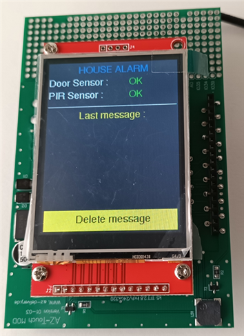
And he comes out of the conditional.
If, on the other hand, when the sensor is checked, the resulting id is 1, it means that the data information has been sent by the motion sensor and the instructions of case 1 will be executed, and these are:
- It will display the message "PIR Sensor Intrusion Detected" on the Serial Monitor.
- Set the font of the text with tft_screen.setFont(&FreeSans9pt7b).
- Set the text size to 1 with tft_screen.setTextSize(1).
- Place the cursor at the coordinates x=150 and y=70 with tft_screen.setCursor(150, 70).
- Set the text color to black tft_screen.setTextColor(ILI9341_BLACK).
- Type the OK text with tft_screen.println("OK") to erase the text at those coordinates if it exists, as the background color of the screen is black just like the text.
- Place the cursor at the x=180 and y=70 coordinates with tft_screen.setCursor(180, 70).
- Set the text color to red tft_screen.setTextColor(ILI9341_RED).
- Write the text Alarm in red with tft_screen.println("Alarm").
- Place the cursor at the x=2 and y=145 coordinates with tft_screen.setCursor(2, 145).
- Set the text color to black tft_screen.setTextColor(ILI9341_BLACK).
- Type the Door Alarm Detected text with tft_screen.println("Door Alarm Detected") to erase the text in those coordinates if it exists, since the background color of the screen is black.
- Place the cursor at the x=2 and y=145 coordinates with tft_screen.setCursor(2, 145).
- Set the text color to red tft_screen.setTextColor(ILI9341_RED).
- Type the text PIR Alamr Detected with tft_screen.println("PIR Alarm Detected").
- The buzzer begins to sound at a frequency of 4000Hz with tone(buzzer, 4000), so it will be ringing until the alarm message is deleted later since we have not configured the time argument, and it comes out of the conditional, since we only have two sensors.
In case the digital pin of the sensors is low, we mentioned before that the else block would be executed, it is easy to follow the execution of the two blocks since they contain similar functions.
Let's now see what to implement to delete the alarm message from the TFT screen and turn off the sound. We have programmed a conditional, since to delete the message we must tap within an area of the TFT screen with a pressure higher than the minimum configured. If you click within the area delimited by the coordinates x>4 and y>280 pixels and a pressure greater than a value of 10, a black box will be drawn on the screen that will have the upper left vertex at the coordinates x=0 and y= 145 and a width of 239 and a height of 30 pixels, so everything inside this box will be deleted. We also changed the state of the microcontroller's GPIO pin with the buzzer connection in the low state, so it will stop playing.
if (touch_screen.touched()) {
	TS_Point p = touch_screen.getPoint();
	if (p.x > 4 && p.y > 280 && p.z > MINPRESSURE) {
		tft_screen.fillRect (0, 145, 239, 30, ILI9341_BLACK);
		digitalWrite(buzzer, LOW);
 }
}
So much for the OnDataRecv statement. Now we start describing the setup() method of the sketch. The first thing we program is the initialization of the Serial Monitor with Serial.begin(115200).
As we did with the ESP8266 of the transmitter modules, we will not use the wireless network of the router so we will disconnect the ESP8266 from the local network with WiFi.disconnect() and configure it as a separate wifi station with WiFi.mode(WIFI_STA).
WiFi.mode(WIFI_STA);
WiFi.disconnect();
We also check if our module ESP8266 has been initialized correctly and we will inform by the Serial Monitor if it does not occur, this we do with the if conditional.
if (esp_now_init() != 0) {
	Serial.print("Error initializing ESP-NOW");
	Return;
}
Once the ESP8266 has been initialized, as this module is the receiver of the data, we must configure it as such with the esp_now_set_self_role(ESP_NOW_ROLE_SLAVE) statement. On the next line we create the esp_now_register_recv_cb(OnDataRecv) record to call the OnDataRecv function when the data is received.
esp_now_set_self_role(ESP_NOW_ROLE_SLAVE);
esp_now_register_send_cb(OnDataRecv);
With the pinMode(TFT_LED, OUTPUT) function, we set the pin of the ESP8266 to which the TFT backlight is connected as the output.
In the following lines we initialize the TFT screen tft_screen.begin() and the "touchscreen" touch_screen.begin(), we display the information on the width (X-axis) and height (Y-axis) of the screen in pixels on the Serial Monitor, and with the last line we fill the entire screen in black.
Serial.print("Init TFT and Touch ...");
tft_screen.begin();
touch_screen.begin();
Serial.print("TFT x = ");
Serial.print(tft_screen.width());
Serial.print("TFT y = ");
Serial.print(tft_screen.height());
tft_screen.fillScreen(ILI9341_BLACK);
With the digitalWrite(TFT_LED, HIGH) line, we change the GPIO pin of the microcontroller to which the TFT display backlight is connected to high state, so that the TFT display will turn on. The rest of the code in the setup() method is very easy to follow, as the static text has been programmed with the font type and size, its coordinates, its color, and the writing of the text on the TFT screen.
In this project, the loop() method is empty.
az_touch_receiver_esp8266 complete sketch
/*-------------------------------------------------------------------------
Alarm project with ZIHATEC AZ-Touch 2.8 inch TFT screen with touch screen,
ESP8266 and ESP-NOW communication protocol.
The components needed are:
- ZIHATEC AZ-Touch 2.8 inch
- PIR sensor
- Hall sensor
- NodeMCU Lua Lolin V3 Module ESP8266 ESP-12F WIFI
- D1 Mini NodeMCU ESP8266
Miguel Torres Gordo
Getafe (Madrid) - ESPAÑA Last revision 02-11-2022
-------------------------------------------------------------------------*/
/*------------ Libraries ------------*/
#include <ESP8266WiFi.h> // Library required for the ESP8266.
#include <espnow.h> // Library required to use the ESP-NOW protocol.
#include <Arduino.h> // Library required to use Arduino fuctions.
#include <SPI.h> // Library SPI communication to use touchscreen.
#include "Adafruit_GFX.h" // Library required to use graphics functions in the the TFT screen.
#include "Adafruit_ILI9341.h" // This is a library for the ILI9341 display products
#include <XPT2046_Touchscreen.h> // Library for the XPT2046 resistive touchscreen controllers
#include <Fonts/FreeSans9pt7b.h> // Bitmap for use the font in the Arduino sketch
#define AZ_TOUCH_MOD_BIG_TFT // AZ-Touch model 2.8 inch touchscreen
/*--- Connection the TFT screen pins to GPIO's pins ESP8266 ---*/
/*** For TFT screen ***/
#define touch_yellow_header // Just a note, the 2.8 inch display has the yellow pin connector
#define TFT_CS 5
#define TFT_DC 4
#define TFT_LED 15
/*** For touchscreen ***/
#define HAVE_TOUCHPAD // Just a note, the screen is touch screen
#define TOUCH_CS 0
#define TOUCH_IRQ 2
/*** For the buzzer ***/
#define buzzer 16
/*------ End pins definition ------*/
/*----- Calibrate touchscreen -----*/
#define MINPRESSURE 10 // Minimun required force for touch event
#define TS_MINX 370 // ADC value of X coordinate = 0
#define TS_MINY 470 // ADC value of Y coordinate = 0
#define TS_MAXX 3700 // ADC value of X coordinate = 239
#define TS_MAXY 3600 // ADC value of Y coordinate = 319
Adafruit_ILI9341 tft_screen = Adafruit_ILI9341(TFT_CS, TFT_DC); // Object implementation for the screen.
XPT2046_Touchscreen touch_screen(TOUCH_CS); // Object implementation for the touch screen.
/*- ESP-NOW development programming -*/
typedef struct sensor_state { // Structure to receiver data from sender modules
int id; // Sender module identity
int value; // Data receiver
} sensor_state;
sensor_state state; // Variable state of type sensor_state to store the variables id and value received
sensor_state hall_sensor; // sensor_state variable for the hall sensor module
sensor_state pir_sensor; // sensor_state variable for the PIR sensor module
sensor_state emiter_boards[2] = {hall_sensor, pir_sensor}; // Arrays with the sender modules structure
/*-- Function called when receive data from sender modules --*/
void OnDataRecv(uint8_t * mac_addr, uint8_t *incomingData, uint8_t len) {
char macStr[18]; // 18-character char type variable
Serial.print("Packet received from: "); // Message on the Serial Monitor
snprintf(macStr, sizeof(macStr), "%02x:%02x:%02x:%02x:%02x:%02x", mac_addr[0], mac_addr[1], mac_addr[2], mac_addr[3], mac_addr[4], mac_addr[5]);
Serial.println(macStr); // Message on the Serial Monitor
memcpy(&state, incomingData, sizeof(state)); // Copy the data from incomingData to state
Serial.printf("Sensor %u: %u bytes\n", state.id, len); // Module number and byte lenght message in the Serial Monitor
emiter_boards[state.id-1].value = state.value; // Value received assign to the module corresponding
Serial.printf("state: %d \n", emiter_boards[state.id-1].value); // Message on the Serial Monitor
Serial.println();
/*-------- Display the information on the tft screen --------*/
/*------ Double conditional to check the value variable -----*/
if(state.value == HIGH) { // If the value is a 1, this block is executed
switch (state.id-1) { // Emitter module check
case 0: // Hall sensor module,the first position in the array
Serial.println("Hall sensor normal situation"); // Message on the Serial Monitor
tft_screen.setFont(&FreeSans9pt7b); // Set font type text to write in the TFT screen
tft_screen.setTextSize(1); // Text size configuration
tft_screen.setCursor(180, 45); // Coordinates to positionate the cursor on the TFT screen
tft_screen.setTextColor(ILI9341_BLACK); // Text color configuration to delete the before text
tft_screen.println("Alarm"); // Write the text in the TFT screen
tft_screen.setCursor(150, 45); // Coordinates to position the cursor on the TFT screen
tft_screen.setTextColor(ILI9341_GREEN); // Text color configuration to write the new text
tft_screen.println("OK"); // Write the text in the TFT screen
break;
case 1: // PIR sensor module,the second position in the array
Serial.println("PIR Sensor Intrusion Detected"); // Message on the Serial Monitor
tft_screen.setFont(&FreeSans9pt7b); // Set font type text to write in the TFT screen
tft_screen.setTextSize(1); // Text size configuration
tft_screen.setCursor(150, 70); // Coordinates to positionate the cursor on the TFT screen
tft_screen.setTextColor(ILI9341_BLACK); // Text color configuration to delete the before text
tft_screen.println("OK"); // Write the text in the TFT screen
tft_screen.setCursor(180, 70); // Coordinates to positionate the cursor on the TFT screen
tft_screen.setTextColor(ILI9341_RED); // Text color configuration to write the new text
tft_screen.println("Alarm"); // Write the text in the TFT screen
tft_screen.setCursor(2, 145); // Coordinates to positionate the cursor on the TFT screen
tft_screen.setTextColor(ILI9341_BLACK); // Text color configuration to delete the before text
tft_screen.println("Door Alarm Detected"); // Write the text in the TFT screen
tft_screen.setCursor(2, 145); // Coordinates to positionate the cursor on the tft screen
tft_screen.setTextColor(ILI9341_RED); // Text color configuration to write the new text
tft_screen.println("PIR Alarm Detected"); // Write the text in the TFT screen
tone(buzzer, 4000); // Activate buzzer sound with 4000Hz tone and infinite time
break; // Exit from the double conditiones
}
} else { // The value is not 1, then this other block is executed
switch (state.id-1) { // Emitter module check
case 0: // Hall sensor module,the first position in the array
Serial.println("Hall Sensor Intrusion Detected "); // Message on the Serial Monitor
tft_screen.setFont(&FreeSans9pt7b); // Set font type text to write in the TFT screen
tft_screen.setTextSize(1); // Text size configuration
tft_screen.setCursor(150, 45); // Coordinates to positionate the cursor on the TFT screen
tft_screen.setTextColor(ILI9341_BLACK); // Text color configuration to delete the before text
tft_screen.println("OK"); // Write the text in the TFT screen
tft_screen.setCursor(180, 45); // Coordinates to positionate the cursor on the TFT screen
tft_screen.setTextColor(ILI9341_RED); // Text color configuration to write the new text
tft_screen.println("Alarm"); // Write the text in the TFT screen
tft_screen.setCursor(2, 145); // Coordinates to positionate the cursor on the TFT screen
tft_screen.setTextColor(ILI9341_BLACK); // Text color configuration to delete the before text
tft_screen.println("PIR Alarm Detected"); // Write the text in the TFT screen
tft_screen.setCursor(2, 145); // Coordinates to positionate the cursor on the TFT screen
tft_screen.setTextColor(ILI9341_RED); // Text color configuration to write the new text
tft_screen.println("Door Alarm Detected"); // Write the text in the TFT screen
tone(buzzer, 4000); // Activate buzzer sound with 4000Hz tone and infinite time
break; // Exit from the double conditiones
case 1: // PIR sensor module,the second position in the array
Serial.println("PIR Sensoe Normal Situation "); // Message on the Serial Monitor
tft_screen.setFont(&FreeSans9pt7b); // Set font type text to write in the TFT screen
tft_screen.setTextSize(1); // Text size configuration
tft_screen.setCursor(180, 70); // Coordinates to positionate the cursor on the TFT screen
tft_screen.setTextColor(ILI9341_BLACK); // Text color configuration to delete the before text
tft_screen.println("Alarm"); // Write the text in the TFT screen
tft_screen.setCursor(150, 70); // Coordinates to positionate the cursor on the TFT screen
tft_screen.setTextColor(ILI9341_GREEN); // Text color configuration to write the new text
tft_screen.println("OK"); // Write the text in the TFT screen
break; // Exit from the double conditiones
}
}
Serial.println(); // Line jump in Serial Monitor
/*-- Process when touching the tft screen to delete message --*/
if (touch_screen.touched()) { // When the screen is touched, the following is executed:
TS_Point p = touch_screen.getPoint(); // Store the coordinates in the variable "p"
if (p.x > 4 && p.y > 280 && p.z > MINPRESSURE) { // If the coordinates are within the values p.x, p.y and p.z, do the following
tft_screen.fillRect (0, 145, 239, 30, ILI9341_BLACK); // Draw a black rectangle with the values of the parameters
digitalWrite(buzzer, LOW); // Pin output to buzzer in low state, sound off
}
}
}
/*---- Method setup() for setting the initial conditions ----*/
void setup() {
Serial.begin(115200); // Serial Monitor initialization
WiFi.mode(WIFI_STA); // Configuration of the ESP8266 module as a wifi station
WiFi.disconnect(); // Disconnect the ESP8266 module from the router's wifi network
if (esp_now_init() != 0) { // If the ESP-NOW protocol does not initialize,
Serial.println("Error initializing ESP-NOW"); // the information is displayed by the Serial Monitor
return;
}
esp_now_set_self_role(ESP_NOW_ROLE_SLAVE); // We configure the ESP8266 as a slave, so that it can receive the information
esp_now_register_recv_cb(OnDataRecv); // When data is received, the OnDataRecv method is called with the data it receives
pinMode(TFT_LED, OUTPUT); // Configuration of the microcontroller port as output for TFT display backlighting
/*-- Initialization of tft screen, touch screen and graphical environment application --*/
Serial.println("Init TFT and Touch ..."); // Information that tft screen and touch screen will be initializate
tft_screen.begin(); // TFT screen initialization
touch_screen.begin(); // Touch screen initialization
Serial.print("TFT x = "); // Message on the Serial Monitor
Serial.print(tft_screen.width()); // Serial Monitor show the width data TFT screen
Serial.print("TFT y = "); // Message on the Serial Monitor
Serial.print(tft_screen.height()); // Serial Monitor show the height data TFT screen
tft_screen.fillScreen(ILI9341_BLACK); // TFT color display with black fill
digitalWrite(TFT_LED, HIGH); // TFT display backlighting is turned on
tft_screen.setFont(&FreeSans9pt7b); // Set font type text to write in the TFT screen
tft_screen.setTextSize(1); // Text size configuration
tft_screen.setCursor(56, 20); // Coordinates to positionate the cursor on the TFT screen
tft_screen.setTextColor(ILI9341_BLUE); // Text color configuration to write text
tft_screen.println("HOUSE ALARM"); // Write the text in the TFT screen
tft_screen.setTextSize(1); // Text size configuration
tft_screen.setCursor(2, 45); // Coordinates to positionate the cursor on the TFT screen
tft_screen.setTextColor(ILI9341_WHITE); // Text color configuration to write text
tft_screen.print("Door Sensor : "); // Write the text in the TFT screen
tft_screen.setTextSize(1); // Text size configuration
tft_screen.setCursor(2, 70); // Coordinates to positionate the cursor on the TFT screen
tft_screen.setTextColor(ILI9341_WHITE); // Text color configuration to write text
tft_screen.print("PIR Sensor : "); // Write the text in the TFT screen
tft_screen.drawFastHLine(2, 87, 236, ILI9341_WHITE); // Draws a line with the coordinates and color of the passed parameters
tft_screen.setTextSize(1); // Text size configuration
tft_screen.setCursor(60, 110); // Coordinates to positionate the cursor on the TFT screen
tft_screen.setTextColor(ILI9341_YELLOW); // Text color configuration to write text
tft_screen.print("Last message :"); // Write the text in the TFT screen
tft_screen.fillRect (4, 280, 232, 36, ILI9341_YELLOW); // Draws a rectangle with the coordinates and color of the passed parameters
tft_screen.setTextSize(1); // Text size configuration
tft_screen.setCursor(60, 301); // Coordinates to positionate the cursor on the TFT screen
tft_screen.setTextColor(ILI9341_BLACK); // Text color configuration to write text
tft_screen.print("Delete message"); // Write the text in the TFT screen
}
/*---- Method loop() ----*/
void loop() { // In this sketch this method is empty
}
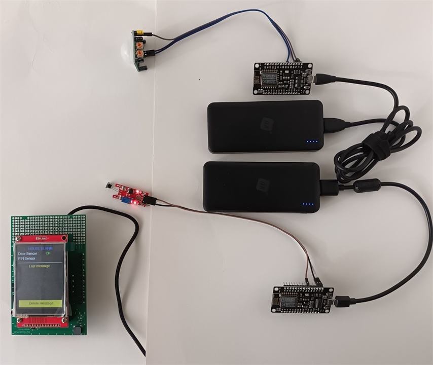
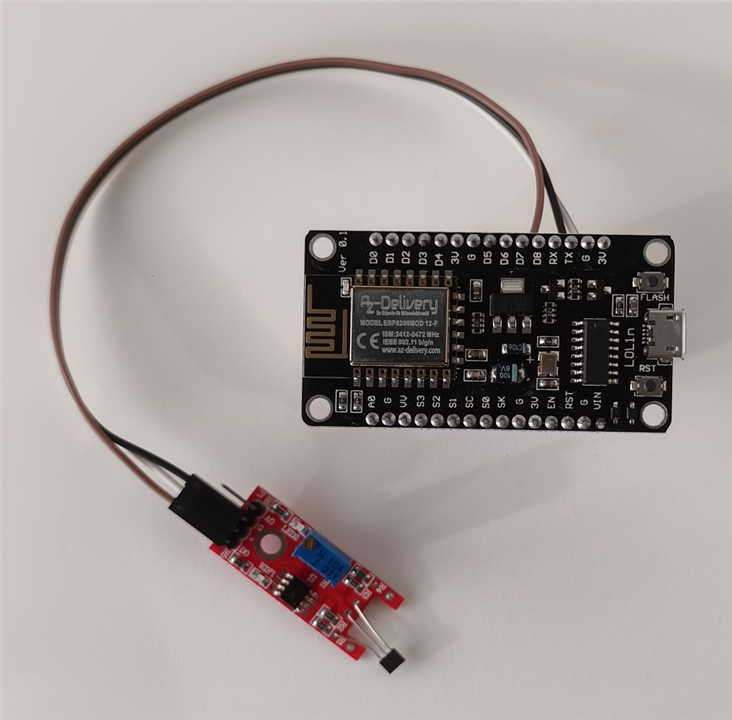
Video showing how the project works