


CWbeacon 14 MHz - An IoT Morse Code Beacon from the IoT Lab to Antarctica
A 3 W HF radio beacon that keys its RF carrier with Morse code, reports its own transmissions over Telegram, authenticates every message with a CRC seeded by Marconi's birthday — and is fully controllable through a web browser OR Telegram, anywhere on Earth.
1. Introduction & Inspiration
In 1895, Guglielmo Marconi conducted his pioneering radio transmission experiments, demonstrating for the first time that signals could travel wirelessly through the air. Today, sending data across the globe via smartphones is second nature. However, understanding the fundamentals of radio frequency (RF) hardware, modulation, and atmospheric signal propagation remains one of the most rewarding challenges in electronics engineering.
To honor Marconi’s legacy and explore the synergy between historical wireless techniques and modern embedded tech, our team at SPARCLAB (the research and engineering laboratory at IIS Cassata Gattapone, a high school in Gubbio, Italy) built the Antarctic Beacon.
The goal was to construct a compact, low-power radio transmitter capable of automatically sending Morse code (CW) messages over the 20-meter amateur radio band (~14 MHz), integrated with modern Internet of Things (IoT) telemetry and control, and to install it at the Concordia Station in Antarctica.
2. From a School Lab in Umbria to the Bottom of the World
The CWbeacon project started at the IoT Lab of IIS Cassata Gattapone in Gubbio, Italy, where students build real-world embedded systems that blend classical radio techniques with modern connectivity. The lab operates under the special call sign IA/IU0SZS, which appears at the start of every Morse transmission this beacon makes.
The project has six hardware and software sub-projects: an RF signal generator board (Si5351A), a 3 W RF power amplifier, a 20 m low-pass filter, a NodeMCU controller board, the firmware described in this post, and a compact 14 MHz antenna. Together they form a self-contained HF station that can be placed anywhere with a power source and a network connection.
The most remarkable deployment so far: Concordia Station, Antarctica. A unit was installed there, where it transmitted its authenticated Morse messages from 75° South — about as far from Gubbio as a radio wave can travel.
IIS Cassata Gattapone, Gubbio, IT

Concordia Station, Dome C, Antarctica

3. Hardware Architecture & Component Breakdown
The complete beacon is built from six modules: Power supply, RF Signal Generator, RF Power Amplifier, Low-Pass Filter, Controller Board, Antenna.
The IoT Lab designed and assembled each module, and you can reproduce it with off-the-shelf components.

3.1. Power Supply: DC/DC Step-Down Converter (12V to 5V)
Converts the incoming main supply voltage (12V) down to a clean 5V line required by the main microcontroller and onboard sub-circuits, ensuring high conversion efficiency and low thermal output.
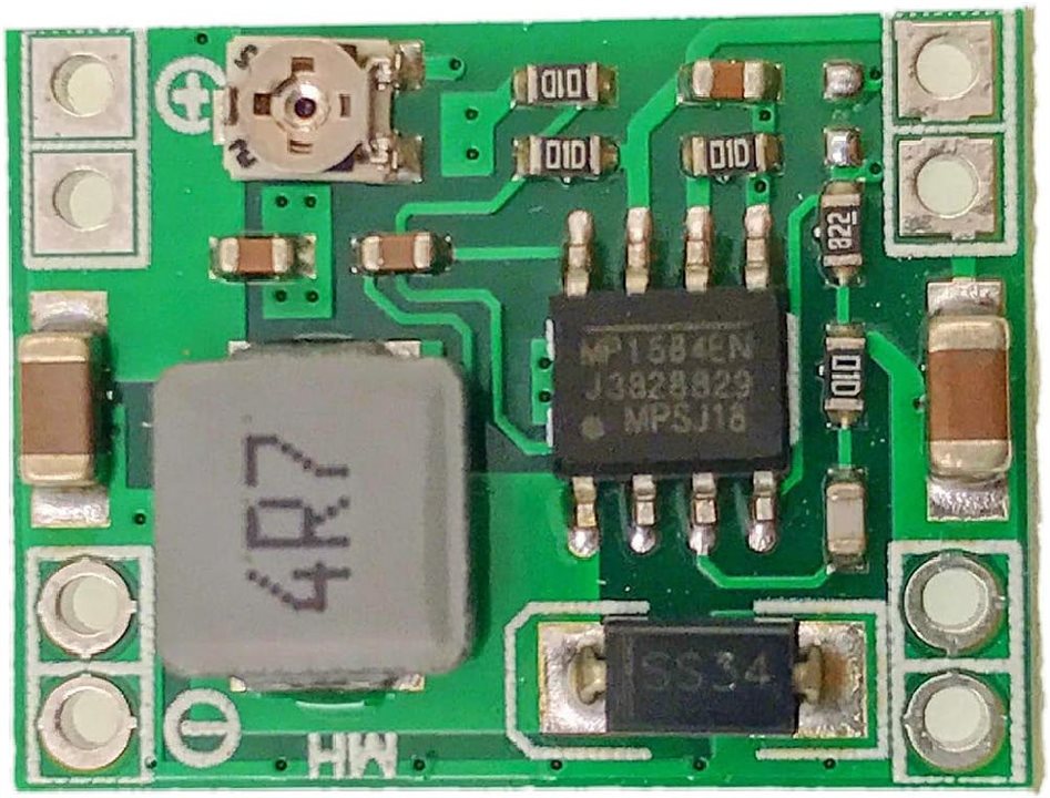
It is based on a small step-down voltage regulator, the MP1584 from MPS, operating at 1.5 MHz, placed on a very small PCB (17 x 22 mm), capable of providing up to 3A of current.
3.2. RF Signal Generator — Si5351A Clock Module
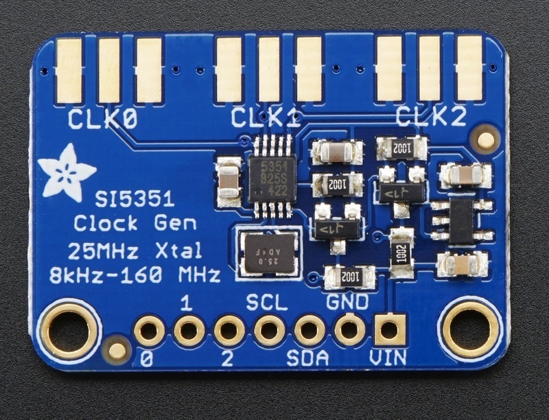
The carrier frequency is generated by an Etherkit Si5351A breakout board, a triple-output programmable clock IC driven over I²C (SDA on GPIO4/D2, SCL on GPIO5/D1).
The CLK0 output is set to 14.097 MHz at startup and can be trimmed via a correction factor stored in EEPROM.
The Si5351A gives excellent frequency stability for a few dollars — far better than a simple crystal oscillator — and its output can be gated on/off in microseconds, which is exactly what Morse keying requires.
3.3. RF Power Amplifier — 3 W Linear Stage
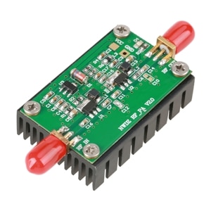
The Si5351A output level (a few milliwatts) is amplified by a small class-AB linear amplifier to approximately 3 W continuous power.
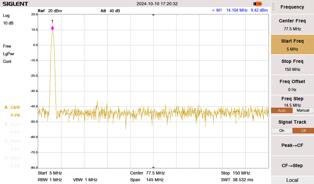
The stage uses a pair of RF transistors in cascade configuration and is biased for good linearity — important for CW (low harmonic distortion; spectral purity matters also for amateur radio regulations).
Here below the RF spectrum of the amplified signal.
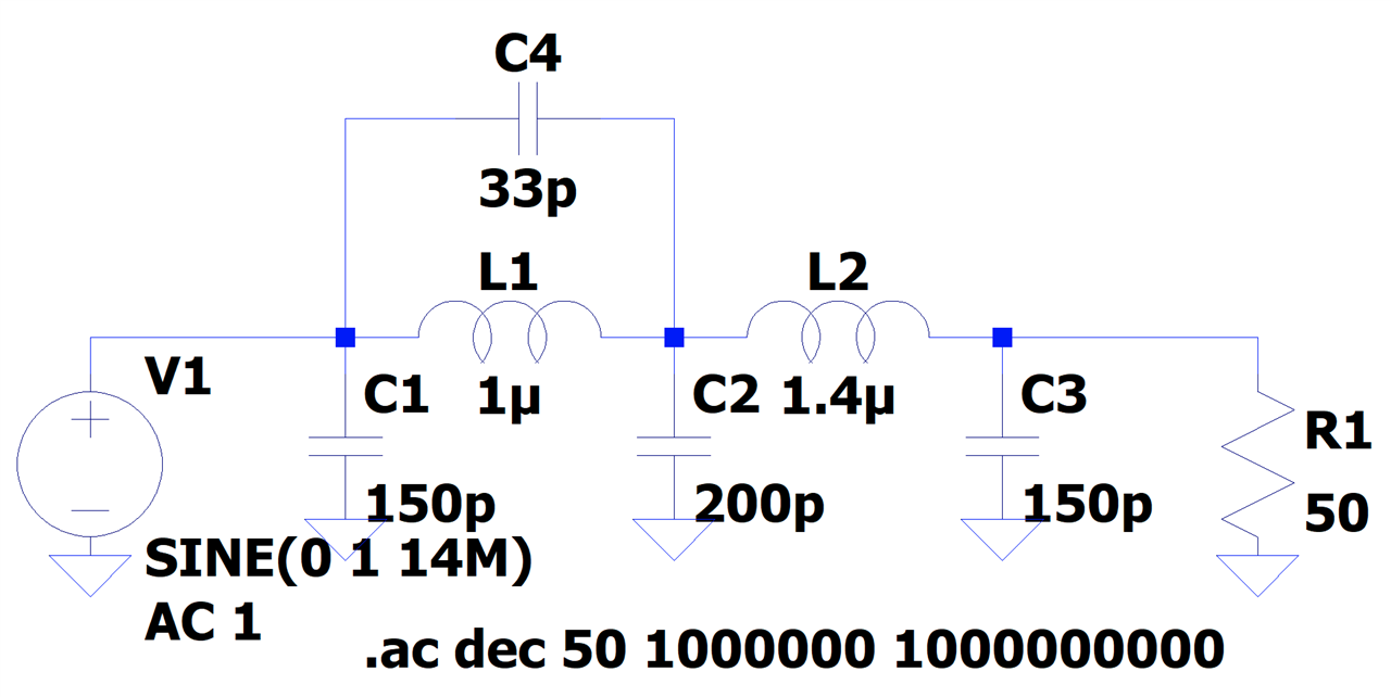
3.4. Filtering: LC Low-Pass and Notch Filter
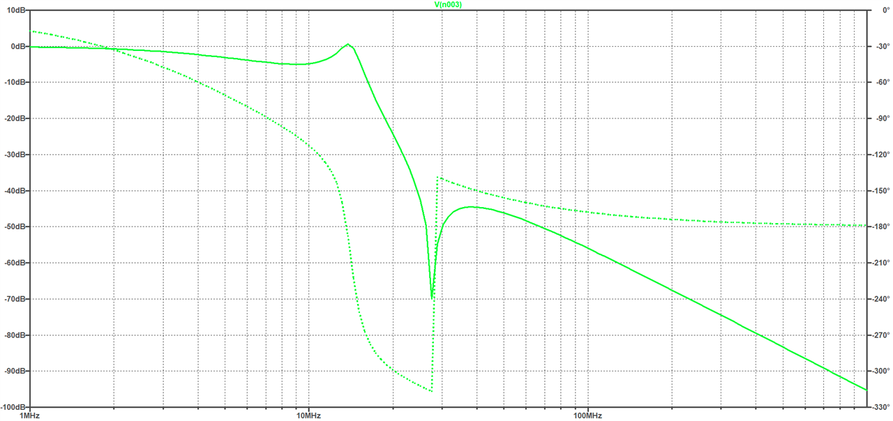
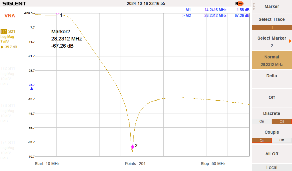
From the image below. we can clearly see the 0 dB attenuation at 14 MHz and the strong effect of the notch filter at 28 MHz, the second harmonic.
3.5. Controller Board — NodeMCU v2 (ESP8266)
The brain of the system is a NodeMCU v2 module carrying an ESP8266 with 4 MB of SPI flash.
It handles the I²C bus to the Si5351A, drives a status LED on GPIO14 that blinks in sync with the Morse carrier, manages Wi-Fi in dual STA/AP mode, and runs the web server, Telegram bot, and NTP client simultaneously.
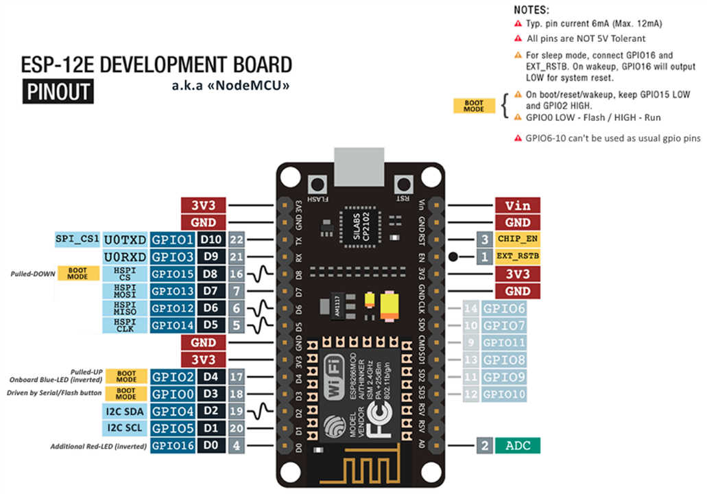
The firmware is described later in this article.
3.6. Antenna System: End-Fed 20-Meter Band Antenna
A half-wave end-fed antenna tuned specifically for the 14 MHz band, providing efficient radiation in harsh Antarctic conditions with a straightforward installation footprint.
An end-fed antenna is essentially a half-wave dipole fed at one end by appropriate matching circuitry, depicted below.
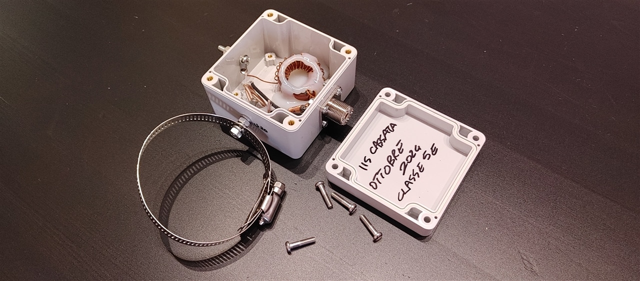
The circuitry of the matching electronics is shown in the following image. It comprises an inductor and a capacitor, opportunely calculated to obtain an impedance of 50 Ohm at the input connector.
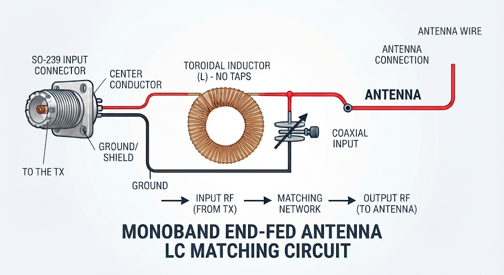
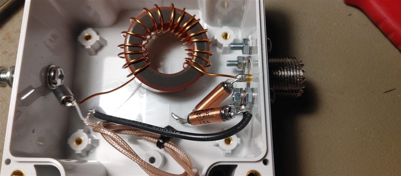
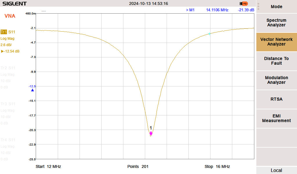
The values of the inductor and the capacitor are, respectively, 4.5 uH and 28 pF. The inductor is obtained with 16 turns of the wire on a T130-2 toroid core, while the capacitor is obtained with 27 cm of a RG316 coaxial cable. The antenna wire length is around 10.14 m. The capacitor and antenna wire length have to be adjusted during the installation to obtain the best resonance possible. The image below shows the very good tuning of the antenna with a very good value of the S11 parameter.
Two more inductors (2 x 56 uH) are connected directly on the coaxial connector: they act as a DC short for electrostatic discharges, very common in very dry environments.
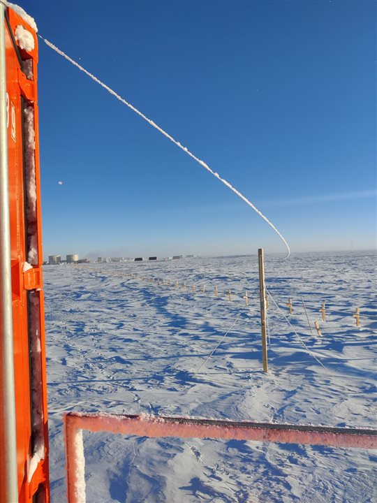
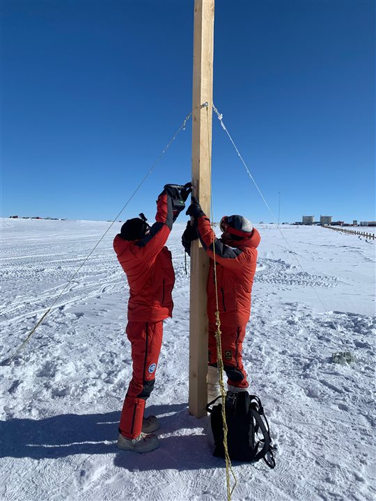
The two images below show the moment the antenna was installed (at around -35°C) at Concordia Station, Dome C, Antarctica.
The wire of the antenna is covered with ice. Given the extreme weather conditions, a special cable has to be used with insulation made of PTFE or FEP; common PVC or other plastics are not suitable for temperatures below -40°C
The antenna is connected to the transmitter with a very good quality coaxial cable, provided for free by one of our sponsors, Messi & Paoloni. We thank them very much for the excellent cable.
4. Final Assembly & Integration Test
All six modules are housed in a compact enclosure. Power-on sequence: the NodeMCU boots, loads all settings from emulated EEPROM, attempts Wi-Fi in STA mode, falls back to AP mode if the network is unreachable, fetches the current time from NTP, composes the beacon message with its embedded CRC, and begins the first Morse transmission within seconds of power-up.
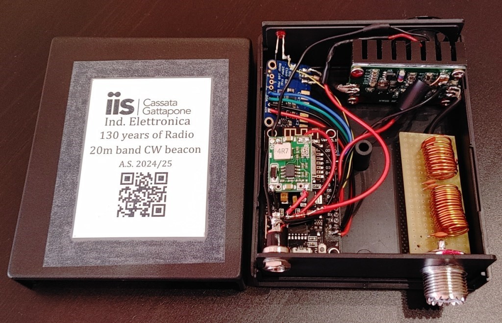
In the following image, from the bottom right to the left: input power connector, DC/DC converter, the NodeMCU, the Si5351 signal generator, and an LED.
In the upper portion of the image, from left to right, we have: a small fan, the RF power amplifier with its heat sink, the LC filter, the SO-239 RF connector.

Bill of Materials (key components)
| Component | Description |
|---|---|
| NodeMCU v2 | ESP8266, 80/160 MHz, 4 MB flash, 802.11 b/g/n Wi-Fi |
| Si5351A module | I²C clock generator, 8 kHz–160 MHz, 3 outputs (Etherkit breakout) |
| RF amplifier | 12 V, ~3 W output at 14 MHz |
| RF filter | LC LPF + Notch |
| LED (GPIO14) | Visual Morse indicator, blinks in sync with RF carrier |
| Antenna | Monoband end-fed half-wavelength, 14 MHz, 50 Ω |
| Power supply | 12V regulated DC, 1000 mA minimum |
6. The Software That Ties It All Together
The firmware runs on the Arduino framework for ESP8266 and is organized around a non-blocking main loop. Every iteration, the Morse sender checks whether it is time to toggle the RF carrier; the web server and Telegram bot check for incoming requests; and the NTP client resynchronizes the clock once per hour.
Morse Keying via Si5351A
The heart of the RF keying is a modified version of the open-source MorseSender library. The key change is in the LEDMorseSender subclass: setOn() and setOff() now simultaneously drive the GPIO pin and enable/disable the Si5351A CLK0 output over I²C:
void LEDMorseSender::setOn() {
  digitalWrite(pin, HIGH);               // LED on
  beacon.output_enable(SI5351_CLK0, 1);  // RF carrier on
}

void LEDMorseSender::setOff() {
  digitalWrite(pin, LOW);                // LED off
  beacon.output_enable(SI5351_CLK0, 0);  // RF carrier off
}
This gives perfectly synchronized visual and RF keying. Timing is PARIS-standard (50 dits per word) at a configurable WPM rate (default 12 WPM).
The Authenticated Beacon Message
Every CW transmission carries three fields:
IA/IU0SZS  130YR PB14QV  A3C2
^^^^^^^^^^^  ^^^^^^^^^^^^^  ^^^^
Call sign    Custom message  CRC
The 4-hex CRC at the end is a Fletcher-16 checksum computed over the current timestamp (yymmddhhmm) concatenated with the constant salt "25041874" — Marconi's birthday, April 25, 1874. Any receiving station that knows the salt and the UTC time can independently verify the checksum, confirming when the transmission occurred and that the beacon has not been tampered with.
Connectivity Features
| Feature | Implementation |
|---|---|
| Wi-Fi | STA mode (joins existing network); automatic fallback to AP mode (SSID: CWbeacon-AP) after ~10 s if no network found |
| Web interface | Built-in HTTP server on port 80; configure all parameters via browser; OTA firmware update at /update |
| Telegram bot | Polls every 5 s via AsyncTelegram2 over BearSSL/TLS; 15 commands; 4 authorized user IDs; bot reports every CW transmission |
| NTP | pool.ntp.org, UTC, resync every hour; required for CRC computation |
| EEPROM | 512 bytes emulated on SPI flash; stores call sign, message, Wi-Fi credentials, Telegram token, frequency correction |
| Serial console | 115200 baud; runtime diagnostics and parameter override without Wi-Fi |
Telegram Bot Commands
The bot gives the operator remote, real-time control of the beacon from anywhere.
Key commands include /status (current transmission, uptime, IP), /start / /stop (enable/disable RF), /setmsg (change the beacon text on the fly), /setfreq (retune within the band), /ntp (force a time resync), /reboot, and /help.
Below is a screenshot of the Telegram app during a conversation with the bot. It also includes a check of the sender, so its use is restricted to very few people.

7. Real-World Results & Propagation Testing
Operating a beacon on the 20-meter band from the Antarctic interior allows radio amateurs and automated tracking networks worldwide to log beacon receptions. This provides practical insights into HF ionospheric propagation, solar activity effects, and signal attenuation in polar conditions.
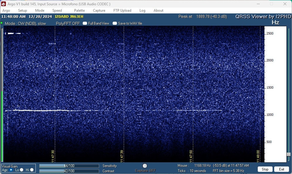
In any case, receiving the weak signal is not easy; the transmit power is only 3W, and the antenna is a single-band end-fed for the 20m band.
Shown below is the spectrogram of the signal received in New Zealand via a web SDR.
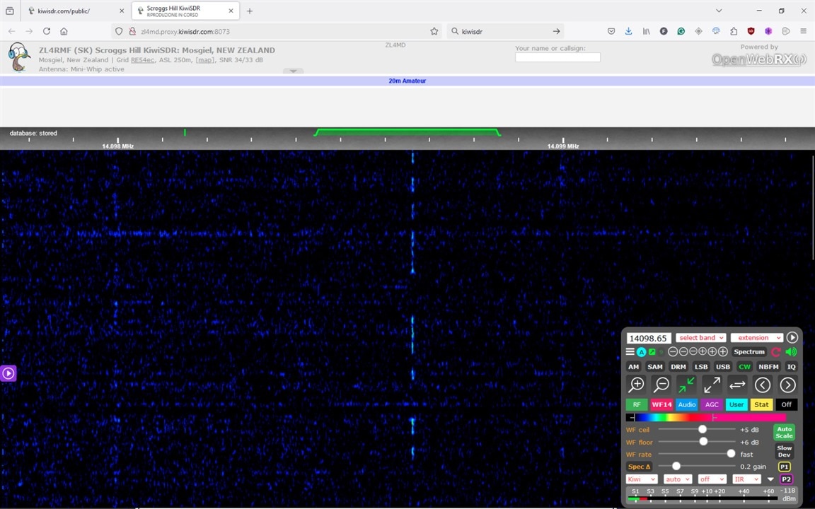
The following image, however, shows the signal received in Italy, over 15,000 km away. A faint trace is visible—one that can only be detected using software designed for receiving slow signals.
8. Conclusion & Educational Impact
Beyond its operational role at Concordia Station, the Antarctic Beacon serves as a hands-on learning platform at SPARCLAB (www.sparclab.it). It demonstrates how stripping away complex abstraction layers down to fundamental RF generation and Morse code can teach core concepts in RF design, impedance matching, power conversion, and IoT control.
Amateur radio has always been about making connections across impossible distances. The CW beacon project takes that idea and layers IoT on top of it: the same microcontroller that keeps the RF carrier on frequency also keeps a Telegram conversation open, serves a web page, and cryptographically signs its own transmissions with a timestamp and a piece of history.
What started as a classroom project to celebrate 130 years of wireless communication ended up on the ice of Antarctica, transmitting a signal that any shortwave listener in the world could receive and decode. That feels, to us, like exactly the kind of connection this contest is about.
Open source — firmware on GitHub
The full firmware source (CWbeaconWeb v1.32), including the modified Morse library and Si5351A driver, is published on GitHub: github.com/Doctor-IoT/CW-beacon
Schematic and PCB files are available on the project blog. The core Morse library is derived from the open-source Arduino Morse library by Stephen Christen, with modifications for Si5351A keying.
Project Links
- Project blog: doctoriot.wordpress.com/beacon-cw-14-mhz-3w/ — full build series (RF generator, amplifier, LPF, firmware, antenna)
- GitHub repository: github.com/Doctor-IoT/CW-beacon — firmware source (CWbeaconWeb v1.32), Morse library, Si5351A driver, README
- IoT Lab: IIS Cassata Gattapone, Gubbio, Italy www.sparclab.it — call sign IA/IU0SZS https://iu0szs.wordpress.com
- Libraries used: ESP8266 Arduino core · Etherkit Si5351 · AsyncTelegram2 · ESP8266HTTPUpdateServer · MorseSender (modified)
Special thanks to Messi & Paoloni for supplying the RF coaxial cable, to TSP S.r.l. for most of the electronic components and measurements, and to the entire Concordia Station staff for their collaboration and the physical installation of the system.


