


This project dates back to the last year of my bachelor degree. The professor for the "Electronic laboratory" course decided to give a twist to final examination allowing two options: standard examination or a project contest. Rules were simple:
- Groups of 3/4 people for each project
- Each group has to realize a project during a predefined time span. At contest date, each group must present the project using slides and then show it working. Judges will be a group of professors.
- Every group that does a project will be excluded from the standard final examination
- Contest winners will be awarded with an extra 3 bonus points on final evaluation
After some discussion with my group, we decided to create a transmitter/receiver pair that uses visible light to transmit information. For the contest purpose, we established that the information will be music, which will make the final presentation more interactive. The last feature we agreed on was an all analog design to include and show the vast majority of knowledge acquired during past courses.
Being a group of four, we divided the circuit into four main blocks:
- Audio input and signal conditioning
- PWM modulator and transmitter
- Receiver
- Demodulator (low pass filter) and output amplifier
Hereafter there are some of the slides shown during the contest presentation. Writings are in Italian (sorry), back then I was not e14 ready  .
.

The PWM modulator was built around the evergreen 555 timer plus a constant current source and a comparator to drive the LED light.
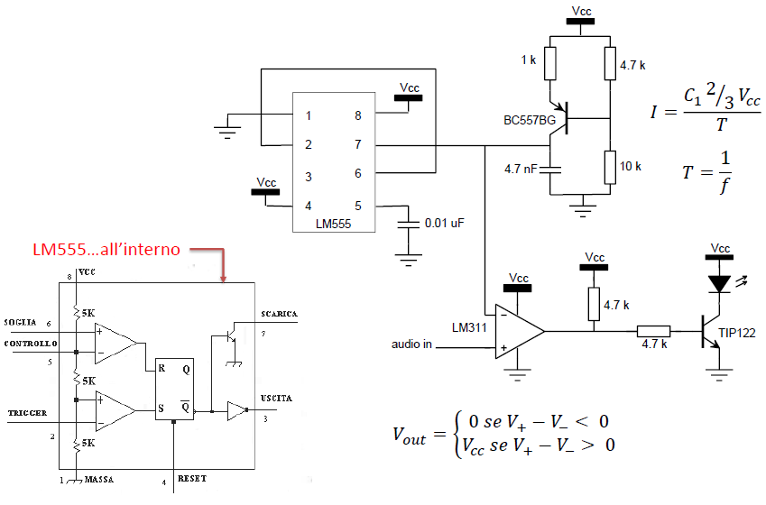
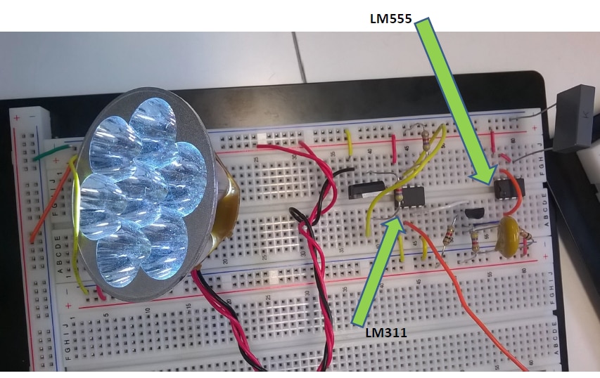
The receiver was based on a transimpedance amplifier, an high pass filter to remove environmental light variation and a comparator to square up the signal.
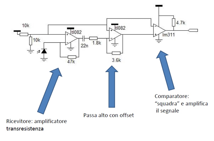
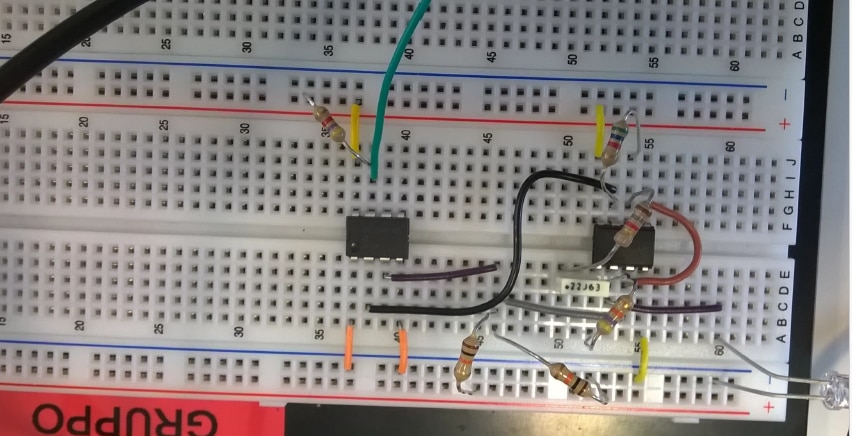
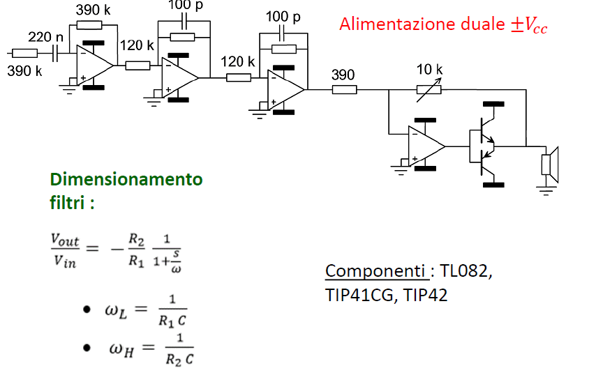
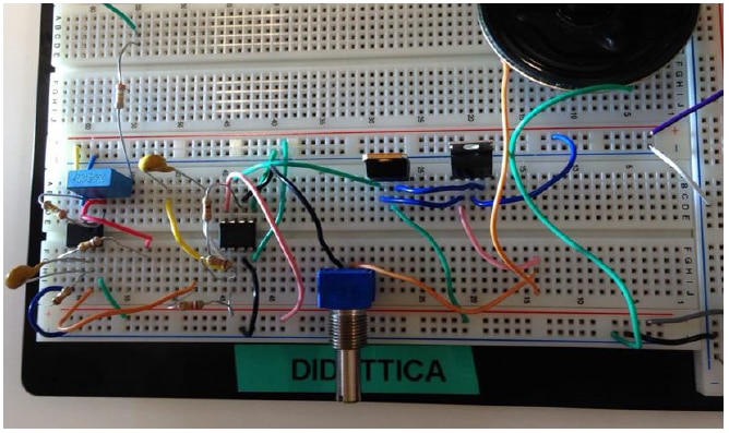
In the end, an high pass filter removes any DC bias, a second order low pass filter demodulates the signal and a power amplifier was used to drive a small speaker.
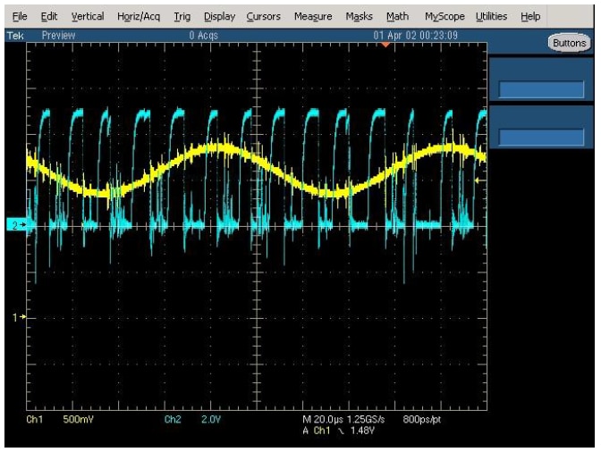
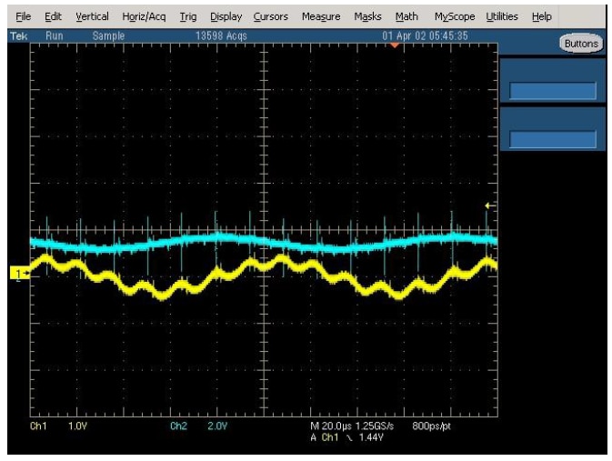
Modulated (first picture in blue) and demodulated waveform (second picture in yellow) were far from perfect, but were good enough to make the circuit work and to give us the contest first place .
This is a short video showing the whole system at work:
Contrary to our initial belief, the project did not end after the contest. Professor asked us and other groups to tidy up our project to show them during department open days, which were scheduled a couple month after the contest finished.
We created two pcbs, transmitter and receiver, and succesfully obtained something that was at least presentable to the public Unfortunately one bodge wire made it from the breadboard to our pcb, try to spot it!

Thanks for reading, I hope you enjoyed it as much as I had fun back then making it!


