


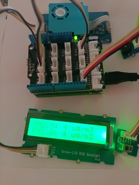
Indoor Air Quality (IAQ) monitoring is crucial for mitigating health risks associated with particulate matter PM1.0, PM2.5, PM10. This system measures airborne particulate matter (PM1.0, PM2.5, and PM10) using an HM3301 Laser Dust Sensor, displays real-time metrics on a Grove RGB Backlight LCD, and features an interactive hardware test mode triggered by a tactile button with acoustic feedback via a piezo buzzer.
1. System Architecture & Physical Layer
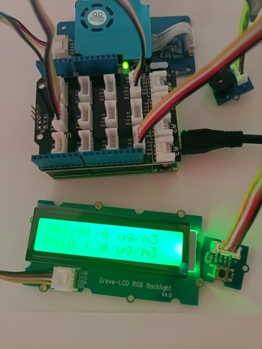
This project utilizes a modular hardware ecosystem designed around the The Things Uno development board. The system integrates laser-based particle sensing, dynamic visual indication via a backlight-controllable display, physical user input, and acoustic feedback mechanisms to deliver a complete ambient monitoring solution.
-
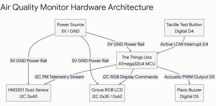
I2C Bus (SDA / SCL): Connected in parallel with the HM3301 sensor (dust concentration readings) and the Grove RGB LCD display (text and backlight color control).
-
Digital Input (D4 - INPUT_PULLUP): Push button connected to ground (GND). Pressing it generates a falling edge (HIGH -> LOW) and triggers the test mode.
-
Digital / PWM Output (D5): Controls the piezoelectric buzzer using audio signals (
tone()) to generate sound notifications. -
Power Bus (5V / GND): Shared power supply line from The Things Uno board for the sensor, display, and auxiliary circuitry.
1.1. Component Breakdown & Technical Characteristics
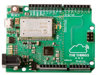
The Things Uno (ATmega32U4 Microcontroller)
-
Architecture: Based on the Arduino Leonardo / ATmega32U4 architecture running at 16 MHz.
-
Integrated I2C Bus: Features dedicated hardware I2C lines hardwired on pins D2 (SDA) and D3 (SCL).
-
Digital I/O & Pull-ups: Offers software-configurable internal pull-up resistors on GPIO pins (utilized on D4 for button debouncing).
-
Connectivity: Includes built-in Microchip LoRaWAN module capabilities for optional long-range IoT data transmission.
Grove - Laser PM2.5 Sensor (HM3301)
-
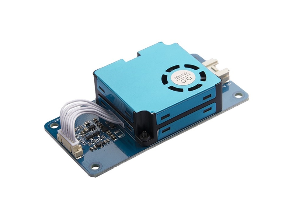
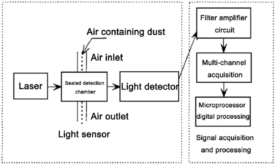
Measurement Principle: Employs laser scattering technology to continuously count suspended particles in the air.
-
Detection Metrics: Simultaneously measures mass concentration for PM1.0, PM2.5, and PM10 (ug/m^3).
-
Communication Protocol: Transmits data via I2C interface at fixed address
0x40using a 29-byte telemetry frame protected by an 8-bit CRC checksum. -
Operating Voltage: Requires a 5V power supply for the internal fan and laser diode driving circuitry.
The system integrates optical scattering measurement with an onboard 32-bit SoC to collect real-time environmental metrics.
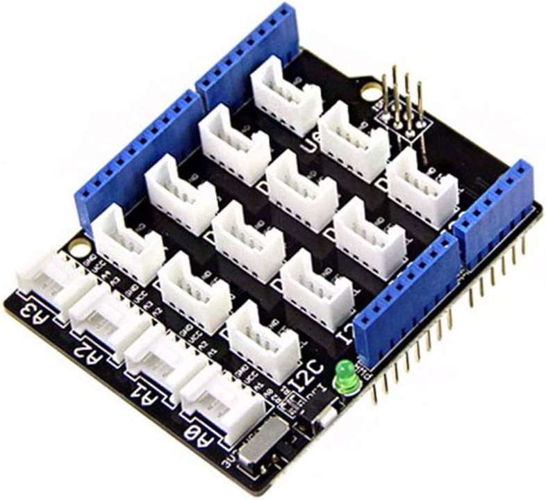
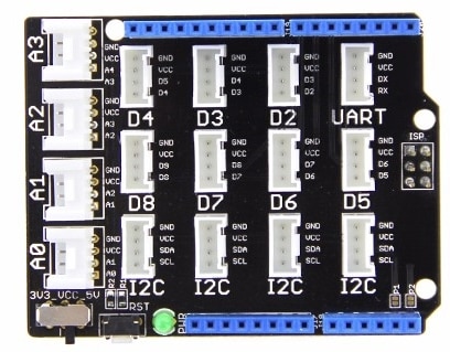
SeeedStudio Base Shield V2 16 x Grove Connectors for Arduino
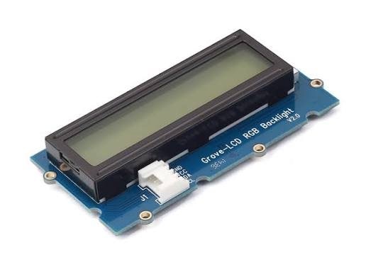
Grove - LCD RGB Backlight (16x2 Characters)
-
Display Capability: Displays 2 rows of 16 monochrome characters for numeric and textual data readout.
-
RGB Backlighting: Features an integrated multi-color LED backlight driver (
PCA9633) controllable over I2C (Address0x62/0x3E). -
Dynamic Indicator: Allows programmatic color switching (Green, Yellow, Orange, Red) to visually reflect WHO Air Quality Index thresholds.
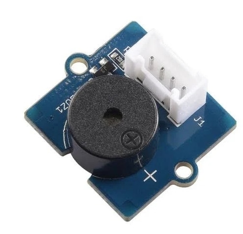
Grove Piezo Buzzer
-
Driver Interface: Connected to pin D5 using square-wave tone generation (
tone()function). -
Audible Alerts: Emits variable-frequency acoustic signals corresponding to system boot completion, simulated alert thresholds during testing, and sequence cancellations.
-
Power Handling: Driven with active low-state cleanup (
digitalWrite(LOW)) to eliminate residual current drain and background high-pitched noise.
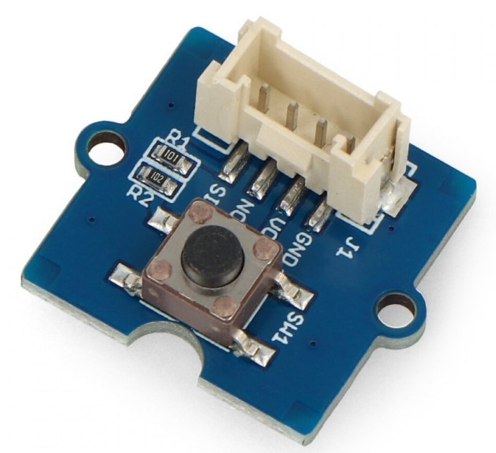
Grove - Button
-
Signal Logic: Configured as an active-LOW digital input connected between pin D4 and GND.
-
Input Sensing: Triggers state changes on falling-edge transitions (transitioning from
HIGHtoLOW) to prevent infinite looping when held. -
Functionality: Provides user-driven execution of the manual RGB and acoustic diagnostic sequence.
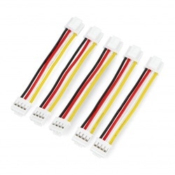
Connection cable Grove 4-pin
1.2 Hardware Specification & Interfacing
The Seeed Studio Grove HM3301 utilizes MIE light scattering theory to count airborne particles. An onboard diode laser illuminates incoming airflow, and a photosensitive detector transforms scattered light into electrical pulses processed into particulate mass concentrations (ug/m^3).
In the Grove PM HM3301 laser sensor, despite the common colloquial use of the term "CRC", the manufacturer actually implemented a simpler and computationally faster Checksum mechanism (an 8-bit byte sum of the data frame).According to the official technical documentation, the sensor transmits a frame consisting of 29 bytes via the I2C bus. The first 28 bytes contain the header and the particulate matter concentration readings, while the final 29th byte (index 28 in the array) stores the checksum.
Checksum Calculation Algorithm
The logic is straightforward: you add up the values of the first 28 bytes of the received data frame. Since the variable storing the sum is an 8-bit type (uint8_t / byte), it automatically overflows (modulo 256). This eliminates the need for complex polynomial division operations. You then compare this calculated value with the byte stored at the end of the frame.
The following function demonstrates how to implement this validation step-by-step directly on the data buffer read from the sensor:
#include <Arduino.h>

// Define the size of the full data frame from the HM3301 sensor
const size_t HM3301_FRAME_SIZE = 29;

/**
 * Function verifying the checksum validity of the HM3301 sensor
 * @param data Pointer to the byte array received from the sensor (min. 29 bytes)
 * @return true if data is valid, false if checksum mismatch occurs
 */
bool verifySensorChecksum(uint8_t *data) {
    // 1. Safeguard against a null pointer
    if (data == nullptr) return false;

    uint8_t calculatedSum = 0;

    // 2. Sum up the first 28 bytes (from index 0 to 27)
    // The uint8_t variable automatically applies modulo 256 upon overflow
    for (size_t i = 0; i < (HM3301_FRAME_SIZE - 1); i++) {
        calculatedSum += data[i];
    }

    // 3. Extract the checksum transmitted by the sensor (byte at index 28)
    uint8_t transmittedChecksum = data[HM3301_FRAME_SIZE - 1];

    // 4. Compare the calculated sum with the received checksum
    if (calculatedSum == transmittedChecksum) {
        return true;  // Transmission successful
    } else {
        return false; // Data corrupted during transmission
    }
}
Main Program Loop Integration (loop)
Here is how to properly utilize this function during your regular sensor data requests to filter out corrupted readings:
int8_t rawBuffer[HM3301_FRAME_SIZE];

void loop() {
    // [Your code to physically read 29 bytes via I2C into rawBuffer goes here]

    // Validate data integrity before processing the measurements
    if (verifySensorChecksum(rawBuffer)) {
        Serial.println("Data valid! Processing PM1.0, PM2.5, and PM10 metrics...");

        // Example of parsing a 16-bit value (PM2.5 occupies bytes 6 and 7)
        uint16_t pm25_value = (rawBuffer[6] << 8) | rawBuffer[7];
        Serial.print("PM2.5: ");
        Serial.print(pm25_value);
        Serial.println(" ug/m3");

    } else {
        // If checksum fails, ignore this data packet (e.g., due to I2C line noise)
        Serial.println("ERROR: Checksum invalid! Data discarded.");
    }

    delay(5000); // Wait 5 seconds before the next measurement
}
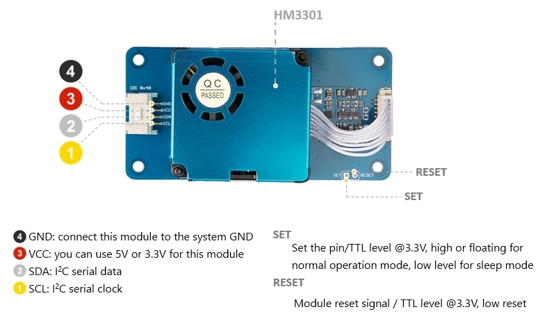
The Arduino operates at 5V logic level while supplying 5V power rails natively via USB or external supply, making it directly compatible with the HM3301's 5V power requirement and signal levels.
| Sensor Pin (HM3301) | Arduino Uno Pin | Function |
| VCC (Pin 1) | 5V | System 5V Power |
| GND (Pin 2) | GND | Ground Reference |
| SCL (Pin 3) | SCL / A5 | i2c Serial Clock |
| SDA (Pin 4) | SDA / A4 | i2cSerial Data |
| SET (Pin 5) | N/C | Pull-up to High (Normal Operation) |
Pin Mapping & Hardware Conflict Resolution
The The Things Uno board uses an ATmega32U4 microcontroller (equivalent to the Arduino Leonardo). On this architecture, digital pins D2 (SDA) and D3 (SCL) are hardwired to the primary hardware I2C bus.
To prevent signal contention between I2C communication and digital I/O:
-
I2C Bus (SDA / SCL): Reserved exclusively for the HM3301 Sensor and RGB LCD Display.
-
Button (D4): Relocated from D2 to D4 to prevent holding SDA low.
-
Buzzer (D5): Relocated from D3 to D5 to prevent outputting I2C clock pulses as audible high-pitched noise.
Wiring & Pinout Guide
| Component | Component Pin / Connector | The Things Uno Board Pin | Connection Notes |
|---|---|---|---|
| HM3301 Sensor | Grove I2C Connector | I2C Port (SDA/SCL) | Powered via 5V rail |
| RGB LCD Display | Grove I2C Connector | I2C Port (SDA/SCL) | Shares I2C bus (Address 0x3E / 0x62) |
| Tactile Button | Terminal A | Digital Pin 4 (D4) | Uses internal INPUT_PULLUP |
| Terminal B | GND | Short to GND on press (diagonal pins) | |
| Piezo Buzzer | Positive (+) Pin | Digital Pin 5 (D5) | PWM / Tone output pin |
| Negative (-) Pin | GND | Ground reference |
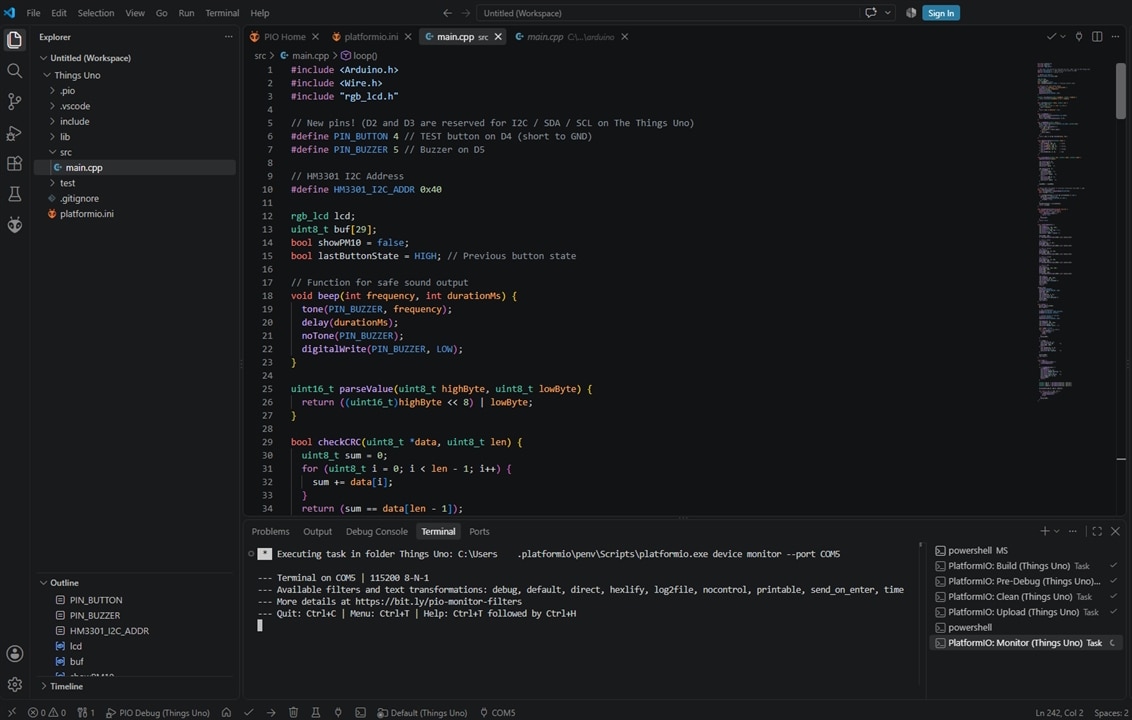
The firmware for this project was developed using Visual Studio Code integrated with the PlatformIO IDE extension. This modern embedded development setup replaces traditional environments like the Arduino IDE, offering professional dependency management, advanced code autocompletion, real-time debugging capabilities, and automated build system integration.
Key Characteristics & Advantages
-
Visual Studio Code (VS Code)
-
Lightweight Code Editor: Provides a fast, flexible, and extensible source code editing environment.
-
IntelliSense & Navigation: Delivers code autocompletion, instant syntax checking, and fast navigation through complex functions and class structures.
-
Built-in Terminal: Allows direct execution of command-line tools, Git operations, and serial communication monitors.
-
-
PlatformIO IDE Extension
-
Automated Dependency Management: Automatically fetches, configures, and tracks third-party libraries (e.g.,
Grove - LCD RGB Backlight) using the project'splatformio.iniconfiguration file. -
Multi-Platform Build System: Handles cross-compilation for various microcontroller targets (in this case, the
atmelavrplatform for the ATmega32U4 chip on The Things Uno). -
Integrated Serial Monitor: Features a built-in terminal for debugging output via USB Serial at customizable baud rates (e.g.,
115200 baud). -
Strict Version Control Integration: Keeps library versions pinned to guarantee consistent builds across different machines and team members.
-
## Development Environment

* **IDE:** Visual Studio Code
* **Ecosystem / Extension:** PlatformIO IDE
* **Framework:** Arduino Framework
* **Platform:** Atmel AVR (`atmelavr`)
* **Target Board:** The Things Uno (ATmega32U4 / Leonardo)
3. Environment Configuration (platformio.ini)
Ensure your environment dependencies and build target are configured correctly:
[env:thethingsuno]
platform = atmelavr
board = leonardo
framework = arduino
monitor_speed = 115200
lib_deps =
    seeed-studio/Grove - LCD RGB Backlight @ ^1.0.0
4. Complete C++ Source Code (src/main.cpp)
/**
 * @file main.cpp
 * @brief HM3301 Air Quality Monitor with Interactive RGB LCD and Acoustic Feedback
 * @target The Things Uno / Arduino Leonardo (ATmega32U4)
 */

#include <Arduino.h>
#include <Wire.h>
#include "rgb_lcd.h"

// Hardware Pin Definitions (Avoid D2/D3 due to ATmega32U4 I2C binding)
#define PIN_BUTTON 4 // Tactile Button connected to D4 (Active LOW)
#define PIN_BUZZER 5 // Piezo Buzzer connected to D5

// Sensor Definitions
#define HM3301_I2C_ADDR 0x40 // Fixed 7-bit address for HM3301

// Global Objects & System Flags
rgb_lcd lcd;
uint8_t sensorBuffer[29];
bool showPM10 = false;
bool lastButtonState = HIGH; // Tracks previous button state for edge detection

/**
 * @brief Emits an acoustic tone on the piezo buzzer and ensures clean pull-down.
 * @param frequency Tone frequency in Hertz.
 * @param durationMs Duration of the tone in milliseconds.
 */
void beep(int frequency, int durationMs) {
  tone(PIN_BUZZER, frequency);
  delay(durationMs);
  noTone(PIN_BUZZER);
  digitalWrite(PIN_BUZZER, LOW);
}

/**
 * @brief Combines two 8-bit registers into a single 16-bit unsigned integer.
 * @param highByte Most Significant Byte (MSB).
 * @param lowByte Least Significant Byte (LSB).
 * @return Combined 16-bit unsigned value.
 */
uint16_t parseValue(uint8_t highByte, uint8_t lowByte) {
  return ((uint16_t)highByte << 8) | lowByte;
}

/**
 * @brief Validates 29-byte packet integrity using 8-bit summation checksum.
 * @param data Pointer to the buffer array.
 * @param len Total length of the packet (29 bytes).
 * @return True if checksum is valid, false otherwise.
 */
bool checkCRC(uint8_t *data, uint8_t len) {
  uint8_t sum = 0;
  for (uint8_t i = 0; i < len - 1; i++) {
    sum += data[i];
  }
  return (sum == data[len - 1]);
}

/**
 * @brief Transmits initialization command to the HM3301 sensor.
 * @return True if I2C transmission succeeds.
 */
bool initHM3301() {
  Wire.beginTransmission(HM3301_I2C_ADDR);
  Wire.write(0x88); // Command byte to initiate measurement cycle
  return (Wire.endTransmission() == 0);
}

/**
 * @brief Reads a complete 29-byte telemetry frame from the sensor over I2C.
 * @param data Target buffer array to store raw bytes.
 * @return True if read count equals 29 and CRC passes.
 */
bool readHM3301(uint8_t *data) {
  Wire.requestFrom((uint8_t)HM3301_I2C_ADDR, (uint8_t)29);
  uint8_t idx = 0;
  while (Wire.available()) {
    if (idx < 29) {
      data[idx++] = Wire.read();
    } else {
      Wire.read(); // Flush extra bytes if any
    }
  }
  return (idx == 29 && checkCRC(data, 29));
}

/**
 * @brief Dynamically alters LCD backlight color based on PM2.5 threshold concentrations (WHO Air Quality Standards).
 * @param pm25 Particulate matter concentration in ug/m3.
 */
void updateScreenColor(uint16_t pm25) {
  if (pm25 <= 12) {
    lcd.setRGB(0, 200, 0);     // Green: Good
  } else if (pm25 <= 35) {
    lcd.setRGB(255, 200, 0);   // Yellow: Moderate
  } else if (pm25 <= 55) {
    lcd.setRGB(255, 80, 0);    // Orange: Unhealthy for Sensitive Groups
  } else {
    lcd.setRGB(255, 0, 0);     // Red: Unhealthy
  }
}

/**
 * @brief Formats and displays particulate matter readings on the 16x2 LCD screen.
 * @param pm1 Concentration of PM1.0 particles.
 * @param pm25 Concentration of PM2.5 particles.
 * @param pm10 Concentration of PM10 particles.
 */
void displayData(uint16_t pm1, uint16_t pm25, uint16_t pm10) {
  updateScreenColor(pm25);

  // Row 0: Static PM2.5 Reading
  lcd.setCursor(0, 0);
  lcd.print("PM2.5: ");
  lcd.print(pm25);
  lcd.print(" ug/m3   ");

  // Row 1: Toggled Reading (PM1.0 vs PM10)
  lcd.setCursor(0, 1);
  if (showPM10) {
    lcd.print("PM10 : ");
    lcd.print(pm10);
    lcd.print(" ug/m3   ");
  } else {
    lcd.print("PM1.0: ");
    lcd.print(pm1);
    lcd.print(" ug/m3   ");
  }

  showPM10 = !showPM10; // Toggle state for next refresh frame
}

/**
 * @brief Non-blocking falling edge detector with software debouncing.
 * @return True ONLY on the initial transition frame from HIGH to LOW.
 */
bool isButtonClicked() {
  bool currentState = digitalRead(PIN_BUTTON);
  bool clicked = false;

  if (lastButtonState == HIGH && currentState == LOW) {
    delay(30); // Debounce sampling interval
    if (digitalRead(PIN_BUTTON) == LOW) {
      clicked = true;
    }
  }
  lastButtonState = currentState;
  return clicked;
}

/**
 * @brief Performs non-blocking delay while actively listening for button presses to interrupt execution.
 * @param ms Duration to delay in milliseconds.
 * @return True if button press was detected during the window.
 */
bool delayWithInterrupt(unsigned long ms) {
  unsigned long start = millis();
  while (millis() - start < ms) {
    if (isButtonClicked()) {
      return true;
    }
    delay(10);
  }
  return false;
}

/**
 * @brief Runs an interactive diagnostic sequence checking display RGB colors and buzzer alerts.
 */
void runTestSequence() {
  lcd.clear();
  lcd.setRGB(255, 255, 255);
  lcd.setCursor(0, 0);
  lcd.print("--- TEST LCD ---");
  lcd.setCursor(0, 1);
  lcd.print(" [BTN] = Cancel ");

  beep(1000, 150);
  if (delayWithInterrupt(1200)) goto cancel_test;

  // Stage 1: Green Test
  lcd.clear();
  displayData(5, 8, 10);
  beep(800, 100);
  if (delayWithInterrupt(1800)) goto cancel_test;

  // Stage 2: Yellow Test
  lcd.clear();
  displayData(18, 25, 30);
  beep(1000, 100);
  if (delayWithInterrupt(1800)) goto cancel_test;

  // Stage 3: Orange Test
  lcd.clear();
  displayData(35, 45, 50);
  beep(1200, 100);
  if (delayWithInterrupt(1800)) goto cancel_test;

  // Stage 4: Red Test
  lcd.clear();
  displayData(85, 120, 150);
  beep(1800, 150);
  delay(100);
  beep(1800, 150);
  if (delayWithInterrupt(1800)) goto cancel_test;

  // Completion
  lcd.clear();
  lcd.setRGB(0, 100, 255);
  lcd.setCursor(0, 0);
  lcd.print("Test finished!");
  delay(1000);
  lcd.clear();
  return;

cancel_test:
  noTone(PIN_BUZZER);
  digitalWrite(PIN_BUZZER, LOW);
  beep(400, 200);
  lcd.clear();
  lcd.setRGB(255, 0, 0);
  lcd.setCursor(0, 0);
  lcd.print("Test Canceled!");
  delay(1000);
  lcd.clear();
}

/**
 * @brief System Initialization Routine
 */
void setup() {
  Serial.begin(115200);
  Wire.begin();

  // GPIO Mode Configurations
  pinMode(PIN_BUTTON, INPUT_PULLUP);
  pinMode(PIN_BUZZER, OUTPUT);

  // Explicit initial driver reset
  noTone(PIN_BUZZER);
  digitalWrite(PIN_BUZZER, LOW);

  // Initialize LCD hardware
  lcd.begin(16, 2);
  lcd.setRGB(0, 100, 255);
  lcd.setCursor(0, 0);
  lcd.print("HM3301 Start...");

  // HM3301 Initialization Retry Loop
  bool ready = false;
  for (int i = 0; i < 5; i++) {
    if (initHM3301()) {
      ready = true;
      break;
    }
    delay(500);
  }

  if (ready) {
    lcd.setCursor(0, 1);
    lcd.print("Init OK         ");
    beep(1500, 100);
  } else {
    lcd.setRGB(255, 0, 0);
    lcd.setCursor(0, 1);
    lcd.print("No response     ");
  }

  delay(1500);
  lcd.clear();
}

/**
 * @brief Main Execution Loop
 */
void loop() {
  // Check for trigger signal
  if (isButtonClicked()) {
    runTestSequence();
  }

  // Poll sensor data frame
  if (!readHM3301(sensorBuffer)) {
    initHM3301();
    lcd.setCursor(0, 0);
    lcd.print("HM3301 Waiting  ");
    lcd.setCursor(0, 1);
    lcd.print("Check I2C/5V    ");
    lcd.setRGB(255, 0, 0);
    delay(1000);
    return;
  }

  // Parse atmospheric values from telemetry payload
  uint16_t pm1_0  = parseValue(sensorBuffer[12], sensorBuffer[13]);
  uint16_t pm2_5  = parseValue(sensorBuffer[14], sensorBuffer[15]);
  uint16_t pm10_0 = parseValue(sensorBuffer[16], sensorBuffer[17]);

  // Update display
  displayData(pm1_0, pm2_5, pm10_0);

  // Responsive delay window (3 seconds total divided into 100ms polling slices)
  for (int i = 0; i < 30; i++) {
    if (isButtonClicked()) {
      runTestSequence();
      break;
    }
    delay(100);
  }
}
5. Software Architecture & Implementation Details
-
Falling Edge State Detection (
isButtonClicked): Uses state-tracking flags (lastButtonState) to execute the test routine only upon initial button actuation. This prevents infinite re-triggering loops if the signal line is grounded continuously. -
Non-Blocking Execution Windows (
delayWithInterrupt): The primary 3-second display cycle and diagnostic test steps break delay routines into short 10ms/100ms polling chunks, allowing the UI to remain fully responsive to user input. -
I2C Packet Integrity Checking (
checkCRC): Evaluates every 29-byte stream returned by the HM3301 against its 8-bit checksum byte (data[28]), dropping malformed data frames automatically. -
Acoustic Driver Safeguard (
beep): ForcesdigitalWrite(PIN_BUZZER, LOW)after clearing tone timers to guarantee the piezo transducer remains completely de-energized during quiet states.
Here is a detailed breakdown of every section and function in the C++ code for your HM3301 particle sensor and Grove LCD project.
5.1. Includes & Pin Definitions
#include <Arduino.h>
#include <Wire.h>
#include "rgb_lcd.h"

#define PIN_BUTTON 4 // TEST button on D4 (short to GND)
#define PIN_BUZZER 5 // Buzzer on D5
#define HM3301_I2C_ADDR 0x40
-
#include <Arduino.h>: Provides standard Arduino functions (pinMode,digitalRead,delay, etc.). -
#include <Wire.h>: Enables I2C hardware communication used by both the LCD and the HM3301 sensor. -
#include "rgb_lcd.h": Library controlling the Grove RGB Backlight LCD. -
PIN_BUTTON&PIN_BUZZER: Reassigns button and buzzer to digital pins D4 and D5 to avoid conflict with I2C pins (D2/SDA and D3/SCL on the ATmega32U4). -
HM3301_I2C_ADDR: The fixed 7-bit I2C address (0x40) for the HM3301 sensor.
5.2. Global Variables & Instances
rgb_lcd lcd;
uint8_t buf[29];
bool showPM10 = false;
bool lastButtonState = HIGH;
-
lcd: Global object to control the display screen and backlight colors. -
buf[29]: Array holding the 29-byte data packet returned by the HM3301 sensor via I2C. -
showPM10: Toggle flag to alternate the second LCD row between PM1.0 and PM10 readings. -
lastButtonState: Tracks the button state from the previous execution frame to implement edge-detection (click logic).
5.3. Buzzer Control (beep)
void beep(int frequency, int durationMs) {
  tone(PIN_BUZZER, frequency);
  delay(durationMs);
  noTone(PIN_BUZZER);
  digitalWrite(PIN_BUZZER, LOW);
}
-
tone(PIN_BUZZER, frequency): Generates a square wave of the specified frequency (in Hz) on pin D5. -
noTone(PIN_BUZZER): Stops audio generation. -
digitalWrite(PIN_BUZZER, LOW): Ensures the pin is driven completely LOW to prevent high-pitched hums or residual current draw.
5.4. Helper Functions: Data Parsing & Checksum
uint16_t parseValue(uint8_t highByte, uint8_t lowByte) {
  return ((uint16_t)highByte << 8) | lowByte;
}

bool checkCRC(uint8_t *data, uint8_t len) {
  uint8_t sum = 0;
  for (uint8_t i = 0; i < len - 1; i++) {
    sum += data[i];
  }
  return (sum == data[len - 1]);
}
-
parseValue(): Combines two 8-bit bytes into a single 16-bit unsigned integer using bit-shifting (<< 8) and bitwise OR (|). -
checkCRC(): Verifies data integrity. It sums the first 28 bytes of the packet and compares the result against the 29th byte (data[28]), which serves as the checksum byte.
5.5. Sensor I2C Communication (initHM3301 & readHM3301)
bool initHM3301() {
  Wire.beginTransmission(HM3301_I2C_ADDR);
  Wire.write(0x88);
  return (Wire.endTransmission() == 0);
}

bool readHM3301(uint8_t *data) {
  Wire.requestFrom((uint8_t)HM3301_I2C_ADDR, (uint8_t)29);
  uint8_t idx = 0;
  while (Wire.available()) {
    if (idx < 29) {
      data[idx++] = Wire.read();
    } else {
      Wire.read();
    }
  }
  return (idx == 29 && checkCRC(data, 29));
}
-
initHM3301(): Sends command byte0x88over I2C to activate the sensor. Returnstrueif transmission succeeds (endTransmission() == 0). -
readHM3301(): Requests 29 bytes from address0x40. Reads bytes intobufand checks validity withcheckCRC().
5.6. Display & Backlight Control
void updateScreenColor(uint16_t pm25) {
  if (pm25 <= 12) {
    lcd.setRGB(0, 200, 0);     // Green (Good air)
  } else if (pm25 <= 35) {
    lcd.setRGB(255, 200, 0);   // Yellow (Moderate)
  } else if (pm25 <= 55) {
    lcd.setRGB(255, 80, 0);    // Orange (Unhealthy for sensitive)
  } else {
    lcd.setRGB(255, 0, 0);     // Red (Unhealthy)
  }
}

void displayData(uint16_t pm1, uint16_t pm25, uint16_t pm10) {
  updateScreenColor(pm25);

  lcd.setCursor(0, 0);
  lcd.print("PM2.5: ");
  lcd.print(pm25);
  lcd.print(" ug/m3   ");

  lcd.setCursor(0, 1);
  if (showPM10) {
    lcd.print("PM10 : ");
    lcd.print(pm10);
    lcd.print(" ug/m3   ");
  } else {
    lcd.print("PM1.0: ");
    lcd.print(pm1);
    lcd.print(" ug/m3   ");
  }

  showPM10 = !showPM10; // Toggles alternate view for next refresh
}
-
updateScreenColor(): Evaluates PM2.5 levels according to WHO air quality index thresholds and updates the RGB backlight color accordingly. -
displayData(): Prints PM2.5 on row 1, and alternates row 2 between PM1.0 and PM10 on each call. Trailing spaces (" ug/m3 ") clear old characters without needinglcd.clear().
5.7. Edge-Triggered Button Input (isButtonClicked)
bool isButtonClicked() {
  bool currentState = digitalRead(PIN_BUTTON);
  bool clicked = false;

  if (lastButtonState == HIGH && currentState == LOW) {
    delay(30); // Software debouncing
    if (digitalRead(PIN_BUTTON) == LOW) {
      clicked = true;
    }
  }
  lastButtonState = currentState;
  return clicked;
}
-
Detects falling edges (transitions from
HIGHtoLOW). -
Debouncing:
delay(30)suppresses mechanical contact bounce. -
Prevents infinite execution loops by registering a trigger only once per physical button press, even if held down or permanently grounded.
5.8. Interruptible Delay (delayWithInterrupt)
bool delayWithInterrupt(unsigned long ms) {
  unsigned long start = millis();
  while (millis() - start < ms) {
    if (isButtonClicked()) {
      return true;
    }
    delay(10);
  }
  return false;
}
-
Replaces blocking
delay()calls during the test sequence. -
Checks
isButtonClicked()every 10 milliseconds. If pressed, returnstrueimmediately to cancel the active sequence.
5.9. Diagnostic Test Routine (runTestSequence)
void runTestSequence() {
  lcd.clear();
  lcd.setRGB(255, 255, 255);
  lcd.setCursor(0, 0);
  lcd.print("--- TEST LCD ---");
  lcd.setCursor(0, 1);
  lcd.print(" [BTN] = Cancel ");

  beep(1000, 150);
  if (delayWithInterrupt(1200)) goto cancel_test;

  // Test sequence runs through simulated AQI levels (Green, Yellow, Orange, Red)
  // ...
  return;

cancel_test:
  noTone(PIN_BUZZER);
  digitalWrite(PIN_BUZZER, LOW);
  beep(400, 200);
  lcd.clear();
  lcd.setRGB(255, 0, 0);
  lcd.setCursor(0, 0);
  lcd.print("Test Canceled!");
  delay(1000);
  lcd.clear();
}
-
Cycles through RGB colors and buzzer alerts to confirm display and sound output function properly.
-
Uses
goto cancel_testto break out cleanly if the user interrupts via button press.
5.10. Initialization (setup)
void setup() {
  Serial.begin(115200);
  Wire.begin();

  pinMode(PIN_BUTTON, INPUT_PULLUP); // Enables internal pull-up resistor
  pinMode(PIN_BUZZER, OUTPUT);

  noTone(PIN_BUZZER);
  digitalWrite(PIN_BUZZER, LOW);

  lcd.begin(16, 2);
  // Initial sensor boot check loop...
}
-
INPUT_PULLUP: Configures pin D4 with an internal resistor pulling it to 5V (HIGH). The button pulls D4 to Ground (LOW) when pressed. -
HM3301 Retry Loop: Attempts initialization up to 5 times before falling back to an error prompt on the LCD.
5.11. Main Application Loop (loop)
void loop() {
  if (isButtonClicked()) {
    runTestSequence();
  }

  if (!readHM3301(buf)) {
    // Re-initialize and display connection error if read fails
    return;
  }

  // Extract PM values from byte buffer (offsets defined in datasheet)
  uint16_t pm1_0  = parseValue(buf[12], buf[13]);
  uint16_t pm2_5  = parseValue(buf[14], buf[15]);
  uint16_t pm10_0 = parseValue(buf[16], buf[17]);

  displayData(pm1_0, pm2_5, pm10_0);

  // Responsive delay loop (3 seconds total) while continuously checking for button presses
  for (int i = 0; i < 30; i++) {
    if (isButtonClicked()) {
      runTestSequence();
      break;
    }
    delay(100);
  }
}
-
Data Parsing: Extracts values from buffer indices:
-
buf[12-13]: PM1.0 atmospheric concentration. -
buf[14-15]: PM2.5 atmospheric concentration. -
buf[16-17]: PM10 atmospheric concentration.
-
-
Non-blocking Loop Delay: Splits the 3-second display update interval into thirty 100ms chunks, ensuring immediate response to user input.
5.12. Visual and Acoustic Indicator Logic
The display features a dynamic RGB backlight that automatically changes color based on the real-time PM2.5 dust concentration levels (measured in ug/m^3), adhering to global Air Quality Standards:
-
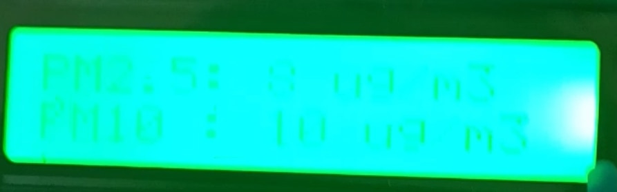
Green (
RGB: 0, 200, 0): Good Air Quality (<12ug/m^3) — Safe levels; standard operation.
-
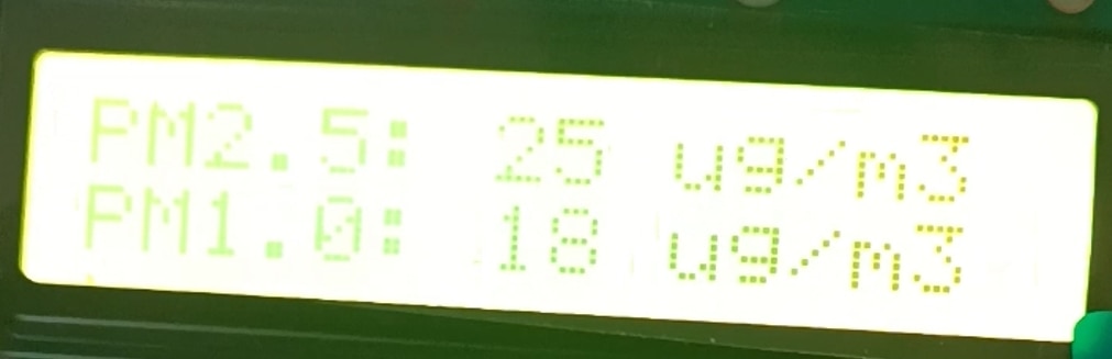
Yellow (
RGB: 255, 200, 0): Moderate Air Quality (13 - 35ug/m^3) — Acceptable air quality.
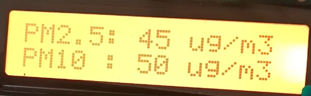
-
Orange (
RGB: 255, 80, 0): Unhealthy for Sensitive Groups (36 - 55ug/m^3) — Elevated pollution levels.
-
Red (
RGB: 255, 0, 0): Unhealthy Air Quality (> 55ug/m^3) — High pollution alert.
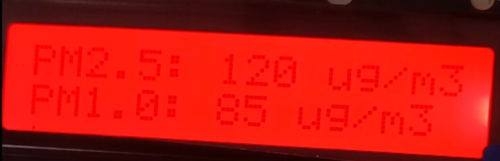
Acoustic Alerts (Buzzer Signals)
In addition to visual color changes, the system provides audible feedback via a piezo buzzer under specific conditions:
-
System Boot / Init OK: Emits a short single beep (1500Hz for 100ms) to confirm successful initialization of the HM3301 sensor.
-
Diagnostic Test Mode: During the self-test sequence, the buzzer sounds at increasing frequencies (800Hz to 1800Hz) corresponding to each simulated air quality level, ending with a double-beep alert on the Red state to confirm alarm functionality.
-
Test Cancellation: Emits a distinct low-pitch tone (400 Hz for 200ms) when the user interrupts or cancels the diagnostic sequence.
6. Experimental Results & Air Quality Index Thresholds
The environmental metrics acquired by the HM3301 sensor correspond to WHO Air Quality Guidelines.
| Parameter | Good | Moderate | Unhealthy / Hazardous | Measurement Unit |
| PM1.0 | 0 - 12 | 13 - 35 | > 35 | ug/m^3 |
| PM2.5 | 0 - 12 | 123 - 35 | > 35 | ug/m^3 |
| PM10.0 | 0 - 54 | 55 - 154 | > 155 |
ug/m^3 |
Conclusion
This implementation establishes a stable, low-latency Indoor Air Quality edge monitoring system. The combination of the The Things Uno module and the optical precision of the Grove HM3301 allows seamless, low-cost sensor deployments suitable for smart home platforms and environmental research.