


Between undergrad and grad school, I had a few months of downtime. I wanted to travel, hang out with friends, and relax, but I was also afraid that my ability to think creatively and solve problems would deteriorate. Around the same time, I saw a YouTube video by an artist of the name Harkish. In the video was a machine called a vertical pen plotter (some of you on this forum might be familiar). He had used a Raspberry Pi and stepper motors to build a contraption that would drag a pen around on a vertical board. The truly impressive part was the algorithms he had written to turn images into unique single-line drawings of smooth curves and continuous spirals. When I saw this, I thought to myself, “I want to figure out how to do that.” Using my basic Arduino knowledge from an intro-level circuits course and my problem-solving skills from some undergraduate research, I set out to build and code a vertical pen plotter that could transform my pictures into one-line masterpieces.
My Plan
The plan was simple. I had a little bit of experience working with an Arduino, and I knew I could learn how to control stepper motors with it. I just needed to figure out a mechanism that could hold a pen against a vertical board, to be moved by the stepper motors. Then I had to figure out how to convert my images into drawing paths that can be recreated by Ink Bot (arguably the most difficult part…). It sounds easy on paper. In reality, I failed, adapted, and learned so much from each of these steps, and I am always open to learning more, so leave a comment if you have any suggestions as you read through!
How it Works
If you watched the short clip at the top of this blog or clicked on the link above for Harkish’s video of his vertical pen plotter (Scribbi) drawing a cat, then you may have an idea of what the mechanism of a vertical pen plotter could look like.
Ink Bot's mechanism consists of a pen held against a piece of paper on a slightly angled vertical board. This pen is held by a component commonly referred to as a gondola. The gondola is weighed down so that the pen presses into the board. Each arm of the gondola connects to belts that run up to and over the stepper motors' pulleys. There are counterweights on the other ends of the belts so that when the stepper motors move, the lengths of the belts connected to the gondola change, causing the pen to move around on the page. An Arduino is used to communicate drawing instructions to the stepper motors. The drawing instructions are generated separately depending on what the desired effect is, and more information about these algorithms is detailed in the next section.
How I Built it
The process I took to build Ink Bot is best broken down into three parts: the electronics, the mechanism, and the code. In the next three subsections, the step-by-step processes for each of these parts are outlined.
The Electronics
As mentioned earlier, I had some experience using an Arduino Uno to control basic circuits from a class I took in college. Controlling stepper motors and SD card readers, however, were things I was completely unfamiliar with. Luckily, I found a webpage by Last Minute Engineers that explained, very simply, how to wire up and use A4988 drivers to control Nema 17 stepper motors, so I ordered some Nema 17s and some A4988 drivers. Similarly, the same website has an article on how to use a microSD card module to expand an Arduino’s storage, so I ordered some HW-125 microSD card readers. Aside from two stepper motors and the SD card reader, the only other component I wanted to add was a push button to tell Ink Bot when to start drawing, which I already had as part of my Arduino starter kit. Here is a schematic of the Arduino circuit:

The stepper motor drivers require 5V power from the Arduino, and 12-24V power from another power source (just be sure to tune the potentiometer on the A4988 drivers to account for the correct voltage, or else they will overheat). I used an old 15V, 44W laptop power cord that had a broken connector as the power supply for the stepper motors.
The Mechanism
The Ink Bot mechanism was mostly built out of repurposed materials, and I encourage anyone trying to recreate this to do the same! The dimensions of your drawing surface don’t matter since you can always adapt your code to account for different geometries. I was lucky enough to have a repurpose store nearby, but you can look around to see what people are getting rid of on Craigslist and Facebook Marketplace, local thrift stores, or even see what kind of junk people leave on the curb. Here is the entire Ink Bot mechanism, broken down piece by piece:

(1) I used an 11/16” thick, 20 ¼” by 34 ¾” board from the repurpose store as the drawing surface, drilling one 1” hole surrounded by four 1/8” holes in each corner to mount the stepper motors as seen below:

The four 1/8” holes were each countersunk since the bolts I had handy for my stepper motors were too short to go through the board.
(2) Then I cut two 3 ½” by ¾” planks at a 14-degree angle to act as the legs to prop up Ink Bot and drilled them into the back of the board at the bottom corners. I also reinforced these with vertical supports made of the same planks, but this was more of an aesthetic choice than anything.

(3) I designed a Gondola (the pen holder) to incorporate used skateboard bearings and had it 3D printed through my school’s design lab.
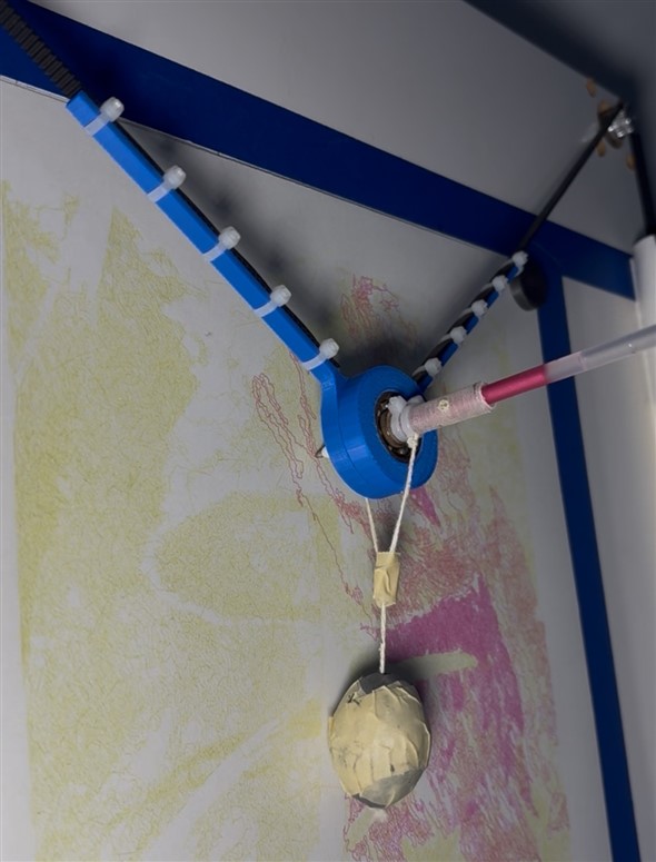
This Gondola was printed after a couple of iterations of prototypes that I built out of tape, cardboard, and old gift cards cut up, so you can get creative with this. There are better gondolas out there, but I wanted to challenge myself by coming up with my own.
(4) I used zip ties to connect the gondola arms to the timing belts, and string to hang the counterweight from the gondola.
(5) Finally, I cut a 1 ½” inner-diameter, 23” long PVC pipe along its length and glued each half along the sides to act as guides for the counterweights, which were attached to the opposite ends of the belts using zip ties and strings.
The entire Ink Bot mechanism is not perfect by far, but that is the beauty of it. It can be made with no overly special tools, for relatively cheap, and it can be programmed to create some pretty impressive drawings.
The Code
The code for Ink Bot can be broken up into two different categories: the code used to turn an image into a drawing path, and the Arduino code used to read the drawing path from an SD card and move the stepper motors accordingly.
Image to Drawing Path
There are many ways to turn a picture into a path for a pen plotter to follow, and it is entirely up to the artist to decide how they want to do this. To keep things brief, I will explain the two main ways that I do this, including example videos.
The first method involves using rows of sine waves to recreate the values or intensities of the pixels in an image. This is done by varying the amplitude and frequency of the sine waves to try to capture how light or dark the region is.
The second method is a bit more chaotic. It involves distributing a bunch of points around an image using a dithering algorithm. This looks just like an art technique called stippling. Then, connecting all those points while trying to create the shortest path possible, a popular concept in computer science called the traveling salesman problem (TSP).
After a drawing path has been created, this path needs to be converted to instructions for Ink Bot to follow. Assuming the drawing paths are in the format of two arrays, one containing the x-values and one containing the y-values, the coordinates can be converted to stepper motor steps using the following Python code (note that I imported numpy as np):
    # converting x,y coordinates to motor step coordinates
    r = 0.5/2 # radius of timing pulley, in
    dtheta = 2*np.pi/200/16 # step angle, rad
    x_0 = 9.0 # x distance to starting point (from either stepper motor, in)
    y_0 = 10.6875 # y distance to starting point (from either stepper motor, in)
    l_0 = np.sqrt(x_0**2+y_0**2+r**2) # initial length of either belt, in
    l_1 = np.sqrt((x_0+allxcoords)**2+(y_0-allycoords)**2)
    l_2 = np.sqrt((x_0-allxcoords)**2+(y_0-allycoords)**2)
    N_1b = np.round((l_0-l_1)/(r*dtheta))
    N_2b = np.round((l_2-l_0)/(r*dtheta))
This code uses Ink Bot's geometry to calculate the number of steps each motor needs to take to change the length of the belt so that the pen moves to a desired x,y coordinate. It assumes that the starting point is along the middle line of the board, evenly spaced between the two stepper motors. The stepper motor coordinates are then saved to a text file where each row alternates between left motor coordinates and right motor coordinates:
    # create text file
    N_12 = np.zeros(len(N_1b)+len(N_2b))
    N_12[0::2] = N_1b
    N_12[1::2] = N_2b
    with open("/Users/Charlie/Documents/Ink Bot/scripts/filename.txt","w") as f:
        for i in range(len(N_12)):
            if i < len(N_12) - 1:
                f.write(f"{int(N_12[i])}\n")
            else:
                f.write(f"{int(N_12[i])}")
This text file is then transferred onto Ink Bot’s microSD card.
The Arduino Code
The whole goal of the Arduino code is to read the series of coordinates from the microSD card, then tell the stepper motors to simultaneously turn to each coordinate. The Multistepper class of the AccelStepper library, in combination with the built-in Arduino SD library, made this a relatively straightforward task. To summarize how the code works, the Arduino opens the text file containing the drawing path. Then, a while loop is used to make the code wait until the button is pressed. Once the button is pressed, the first two lines of the text file are each parsed, and the motor is told to move to the corresponding stepper motor coordinate. This is used to position the pen at the starting point, so the cap is usually left on the pen for this. At the first point, the code waits again for a button press to start the drawing so that the cap can be taken off and the pen placed against the paper. Once the button is pressed this time, a while loop is used to parse every two lines of the text file and move the steppers to the coordinate until there are no more lines to parse in the text file. At this point, Ink Bot stops drawing and waits for the user to put the cap back on and press a button to return to the starting point. Below is the commented Arduino code:
// Include the AccelStepper Library
#include <AccelStepper.h>
#include <MultiStepper.h>
// Include the SD and SPI libraries
#include <SPI.h>
#include <SD.h>

// Define pin connections
const int dirPin1 = 4;
const int stepPin1 = 5;
const int dirPin2 = 2;
const int stepPin2 = 3;
const int onpin = 8;
const int chipSelect = 10;

// Define File from SD card
File script;

// Change this to whatever the script is named
String filename = "filename.txt";

// Define motor interface type
#define motorInterfaceType 1

// Create AccelStepper instances
AccelStepper stepper1(motorInterfaceType, stepPin1, dirPin1);
AccelStepper stepper2(motorInterfaceType, stepPin2, dirPin2);

// Create MultiStepper instance
MultiStepper motors;

void setup() {
  // Set up pins as outputs
  pinMode(stepPin1, OUTPUT);
  pinMode(dirPin1, OUTPUT);
  pinMode(stepPin2, OUTPUT);
  pinMode(dirPin2, OUTPUT);
  // Set initial states to LOW
  digitalWrite(stepPin1, LOW);
  digitalWrite(dirPin1, LOW);
  digitalWrite(stepPin2, LOW);
  digitalWrite(dirPin2, LOW);
  // Begin serial connection
  Serial.begin(9600);
  while (!Serial) {
    ; // wait for serial port to connect.
  }
  Serial.println("Serial connection established.");
  // Initialize SD card
  Serial.print("Initializing SD card...");
  if (!SD.begin()) {
    Serial.println("initialization failed.");
    return;
  }
  Serial.println("initialization done.");
  // Configure stepper1 and stepper2
  stepper1.setMaxSpeed(1500);
  stepper2.setMaxSpeed(1500);
  // give them to MultiStepper to manage
  motors.addStepper(stepper1);
  motors.addStepper(stepper2);
  // setup start button
  pinMode(onpin, INPUT);
}

void loop() {
  // open file on SD card
  script = SD.open(filename);
  if (script) {
    Serial.println("File opened");
  }
  else {
    Serial.println("Error opening file");
    return;
  }
  // wait for button press to move to first point
  Serial.println("Press button to move to first point");
  int switchstate = digitalRead(onpin);
  while (true) {
    switchstate = digitalRead(onpin);
    if (switchstate == HIGH) {
      break;
    }
  }
  // Move to first point
  long point[2];
  point[0] = script.parseInt();
  point[1] = script.parseInt();
  motors.moveTo(point);
  motors.runSpeedToPosition();
  // wait for button press to begin printing
  Serial.println("Press button to begin printing");
  while (true) {
    switchstate = digitalRead(onpin);
    if (switchstate == HIGH) {
      break;
    }
  }
  // loop through each point and move steppers to each
  while (script.available()) {
    point[0] = script.parseInt();
    point[1] = script.parseInt();
    motors.moveTo(point);
    motors.runSpeedToPosition();
  }
  // close file on SD card
  script.close();
  // wait for button press to return to origin
  Serial.println("Drawing complete. Press button to return home");
  while (true) {
    switchstate = digitalRead(onpin);
    if (switchstate == HIGH) {
      break;
    }
  }
  // return to origin
  point[0] = 0;
  point[1] = 1;
  motors.moveTo(point);
  motors.runSpeedToPosition();
  while (true) {};
}
Keep in mind that I am far from an expert in C++. I wrote this code based on what I read on the Last Minute Engineer webpages I mentioned earlier and from scouring the Arduino forums. I have since then realized that I could’ve utilized the setup and loop portions of the code much better. It does the trick, but good enough is the enemy of great, so any suggestions from the experts on here are definitely welcome.
Problems I ran into
I ran into more problems throughout building Ink Bot than I could ever hope to document on here, but each problem was a fantastic opportunity to learn from, so I will start with a few of the main ones:
USB Serial Communication
This was another entirely new concept to me that was quite difficult to get working. I wanted to send the drawing coordinates from my computer over to Ink Bot (to the Arduino) using USB serial communication. Figuring out how to get the Arduino to read the data correctly was an issue in itself, but when I finally got it working, it was extremely slow. I know there are better/faster ways to do this, but the solution I landed on was to use an SD card reader connected directly to the Arduino. This way, I could put the entire drawing path file on the microSD card, and Ink Bot could easily and quickly read it line by line while feeding the coordinates to the stepper motors. I quickly found out that any blank lines left at the end of a text file were interpreted as a 0 by my code. This led to Ink Bot drawing a line back to the origin at the end of its drawing, but luckily, this was an easy fix (I just made sure to end the text file on the last number value, not on a blank line). Overall, the SD card reader made life a lot easier and sped Ink Bot up to the point where it was only limited by its physical mechanism.
SD Card Reader
I kept running into issues where Ink Bot would either (1) be unable to open the file on the SD card or (2) would stop in the middle of a drawing and return to the origin. It took me quite a while to figure these problems out, but after lots of trial and error and scouring internet forums, I found the sources of these two problems: (1) my filenames were sometimes too long for the Arduino SD library. This library uses an old filename format that requires all filenames to be 8 characters or less (not including the .txt extension). This could easily be fixed by using a different library, but instead, I just strictly limit my filenames to 8 characters now. (2) Ink Bot stopping in the middle of a drawing turned out to be because of the SD card reader dropping out sometimes mid-drawing. I read online that this can often happen when powering your Arduino through your computer's USB, and the solution was to add a capacitor parallel to the SD card reader's VCC and GND pins to smooth out any sharp voltage changes.
Various Mechanical Issues
I won’t go into too much detail here, but designing the gondola and finding the right amount of counterweight to use were challenges that just required some iterative design and trial and error to work through. To prove it to you, here are some pictures of the first two gondola iterations:

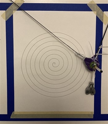
The first gondola was made entirely out of cardboard and painter's tape, and the second was made using cut-up and glued-together hotel key cards. These iterations helped me figure out the geometry needed for the 3D printed gondola.
Calibration
Speed and position calibration were also problems that required some good old trial and error. I printed the same picture over and over again using a ton of different max stepper motor speeds and landed on one that I think has a good balance between the time it takes to print and the shakiness in the pen lines. For position calibration, I printed a large rectangle over and over again while tweaking Ink Bot’s geometry in the code that converts the x,y coordinates to stepper motor steps. I did this until the rectangle’s side lengths matched the prescribed side lengths almost perfectly.
Concluding Remarks
And that is about it! Ink Bot may seem simple compared to many high-tech CNC plotters out there, but that is the whole point. Anyone can build one with limited tools and supplies and start making some very unique art. If you read this far and are interested in Ink Bot and my journey making art, then give me a follow @nimion_art on Instagram or TikTok. If you want to build a vertical pen plotter of your own, then feel free to take inspiration from Ink Bot, and remember to get creative and question all of my design choices, because there are so many different ways it can be done!


