


When it comes to work projects, 80% of the time for my primary MCU I work with STM32 family chips, 15% I work with Nordic Semiconductor SOCs, and the last 5% is something very specific. And when it comes to hobby it's a mixed bag. Given the large percentage of STM32, I had invested in an STLink V3, in fact I have access to two (one belonging to my College), and I use an nRF52 DK to program the nRF52 on custom boards using 6 individual male-male jumper wires. But as the scale of the work started increasing and the types of clients increased, it became more work-intensive to switch between different programming interfaces and cables.
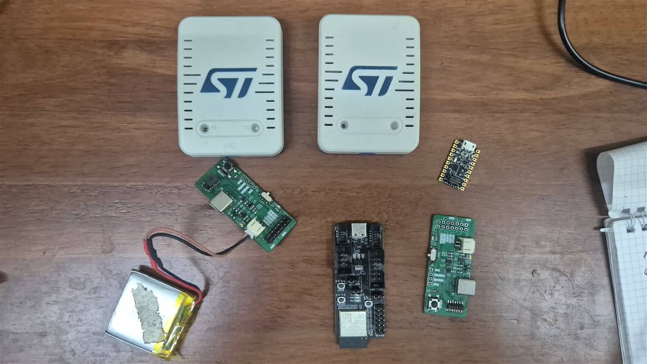
Now, the STLink V3 has an STDC14 connector and comes with two cables - STDC14 to STDC14 and STDC14 to ARM10 - they both have a 1.27mm spacing. But some clients wanted 2.54mm connectors, either in IDC format or simply a bare minimal 4-pin connector like the one seen on Blue Pills. There was another requirement: the STLink V3 does not power the board, it only has a VCC pin to detect the voltage level. There were times when the assembly process of clients required the board to be programmed before the battery is attached, and without an additional connector/test point to power the board, it became difficult. So last year, to handle the 1.27mm/2.54mm and the power issue, I made an interface board. This has a LiPo with an MCP73831 charger and ideal-FET power path, this way I can choose to power the actual board, all using one IDC connector.
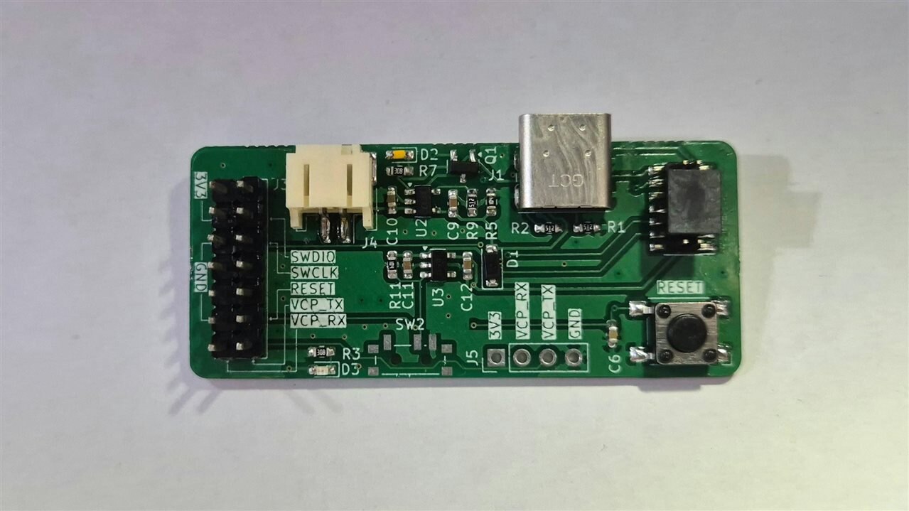
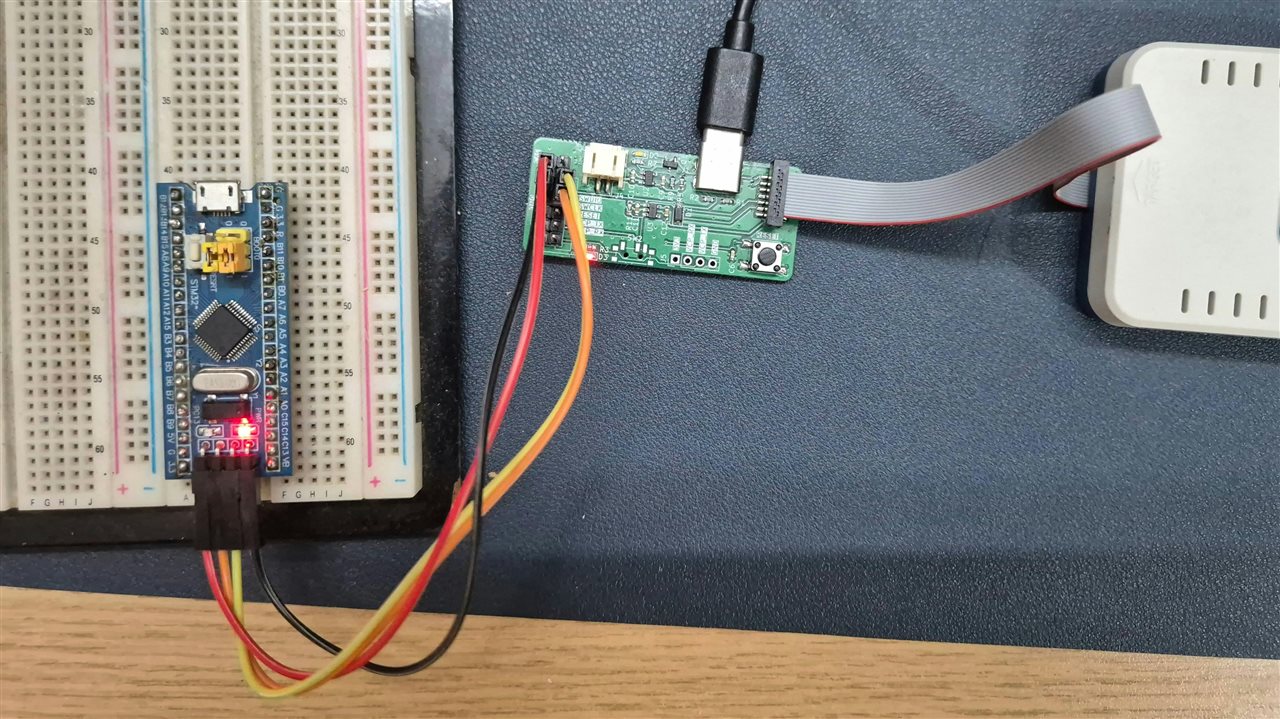
As clients grew, The problem grew too. Some had a good budget to invest in a JLink or an STLink V3, some would not. Some needed more than one programmer. So I decided to make one programmer with the following functions. This would help me make one common documentation and flash script for all the client projects. Now, this is a product I am making, not a project, so I am seeing this from the customer/client perspective. As a developer, many of their concerns are not my problem.
- Program the MCU using the connector interface of their choice using OpenOCD
- Power the MCU for programming if needed. Both 5V and 3.3V
- Basic Debugging of MCU. (I can remotely check the traces), High speed not required
- USB-UART Bridge
- Efuse Protect the 5V and 3.3V power in case of accidental shorts
- ESD Protect all connectors to save the programmer
- Easy Status identification using LEDs
- Minimum or Zero Firmware development of the Programmer.
The easy choice would be ARM DAPLink, but I needed time to go through the code. I wanted a lazy solution, so I noticed that WeAct's DAPLink had the binary directly on their GitHub page along with their schematic. So it was chosen. All I had to do was build around their schematic, use the exact pins. The WeAct DAPLink lacks some features compared to the official DAPLink, drag-and-drop being the top one, but I usually rely on batch scripts to program, open a COM port, get some data out of the MCU, all in one shot, so the loss of drag-and-drop was not a deal breaker. I did ask ChatGPT whether I could adapt ARM's DAPLink to the schematic of the WeAct board, and it said it's fine. But anyway my first priority is to get a prototype of this programmer out to a couple of clients and see how they use it, updating the design only if needed.
Coming to usability, after talking to a couple of heavy users, I decided to copy the STLink V3: have the STDC14 connector at the bottom along with the ARM10. For the 2.54mm connectors, I'll have one row of male and one row of female connectors, that way it's more flexible. Also, in rare cases where clock jitter is causing corruption of the UART lines, I can attach a logic analyzer to debug it while using the 2.54mm connectors.
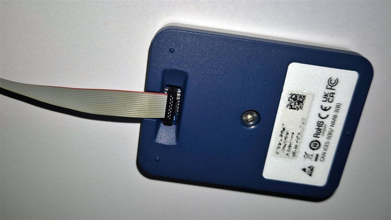
Underside of he STLINK V3
3 groups of 2.54mm connectors have been planned: a 5V + GND set, a 3.3V + GND set, and another set with the SWD + UART connectors. Plenty of pins to use. I did drop the LiPo battery, because in the last design it became more of a hassle to place the LiPo safely away from the header pins that could poke it. And also, with the current design we're powering the programmer and the board using one USB, so it's no longer needed.
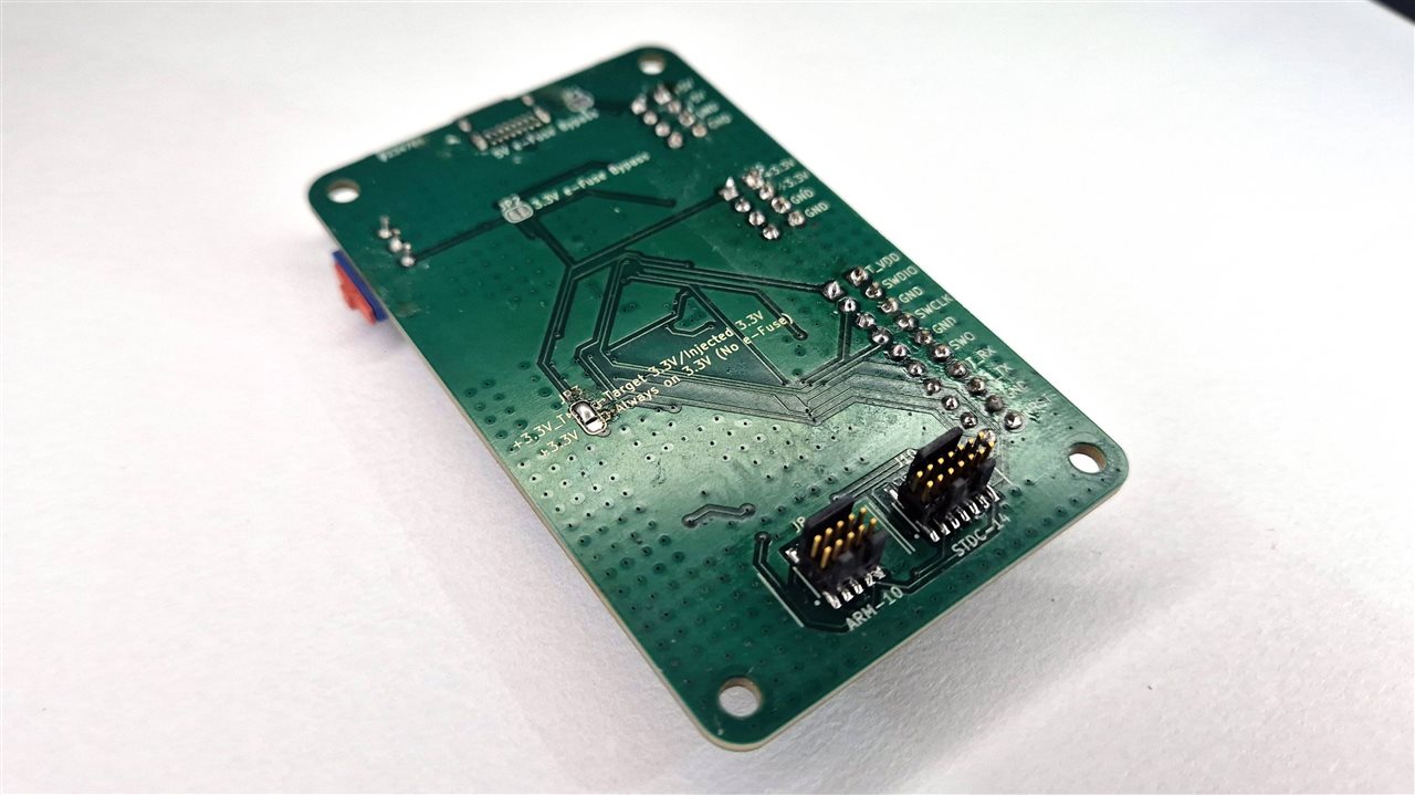
Once I actually sat down with the WeAct schematic and started building around it, the connector count grew past what I'd originally sketched. I ended up with 5 physical debug connectors instead of just the STDC14 + ARM10 pair I described above - the primary ARM10 at 1.27mm pitch, the STDC14, a legacy 2.54mm ARM10 header for the DIY/breadboard crowd, a bare 1x6 SWD header for quick and dirty debugging, and a Tag-Connect TC2030 pogo-pad footprint for production programming where you don't want a connector left on the finished board at all. All of them ride the same internal signal bus (SWDIO/SWCLK/SWO/NRST/VTREF/GND, UART where the connector has the pins for it) so nothing had to be special-cased in firmware to support all five.


WeAct's DAPLink Schematic taken from: https://github.com/WeActStudio/WeActStudio.MiniDebugger
On the requirement list above, a few of these deserve their own explanation now that they're actually designed instead of just planned.
EFuse and ESD Protection
I used two separate TPS25200DRV eFuses rather than one. One sits right on the USB input (VBUS), protecting the programmer itself and the upstream USB host if something on my side ever shorts. The second one sits on the target-power output specifically, so a shorted client board trips its own independent limit without taking the whole programmer down with it, and it has its own fault LED so I can tell at a glance which side actually faulted. USBLC6-2SC6 handles ESD on the USB D+/D-/VBUS lines, placed right at the connector before anything else touches those lines. There is also ESD Protection by TPD4E05U06DQA for the programming connectors. But Placement wise on PCB, I had to compromise a little but. TPD4E05U06DQA's datasheet recommends that I keep it close to the connectors, but i kept it at the junction where the signal lines from MCU Split into 3, one each for the different connectors. It is my educated guess that the reason why the Datasheet recommends it close to connectors is to avoid the ESD surge disrupting other signals. But on my board, there is no other parts or signals, So i Guess its okay.
Powering the target board
I used two different rails. The 3.3V target power goes through the dedicated Target Power Switch (TPS25200DRV #2, OFF/3.3V modes, EN-controlled, its own current limit and fault LED). 5V is simpler than that - it's just the +5V rail itself, taken straight off USB and already protected by the input eFuse (TPS25200DRV #1) on the way in, broken out on its own header (J4) with its own GND pins. So it's always-on and eFuse-protected rather than switched, but the requirement is met: a target can be powered at 5V or 3.3V, both protected against accidental shorts.
Status LEDs
5 In total: a plain always-on power LED, the debug/activity LED , a target-power good LED plus its own fault LED, and TX/RX UART activity LEDs. The UART LEDs were the fiddly bit - I didn't want to load the UART lines at all, so instead of tapping them electrically in a way that could affect signal integrity, each one is sensed through a transistor biased off the line itself, dark when idle and only lighting on actual traffic.
Target Voltage Sense
One extra thing came out of poking at the schematic that I hadn't planned: PA0, which on the stock WeAct board is just hardwired to a fixed ~1.65V reference off VDD33 for reasons I still don't fully know (self-test or board ID, maybe), is now brought out through a solder jumper (JP3) onto the legacy 2.54mm connector's VTREF pin. Left open, it lets the MCU sense whatever voltage a self-powered target is presenting (halved through a resistor divider so it stays safely in range) - basically a free voltage-sense feature I get for reusing a pin stock firmware doesn't otherwise care about. Bridged one way it reproduces the original stock behavior exactly, bridged the other way it ties into the target-power switch's own output.
Here is my final Schematic

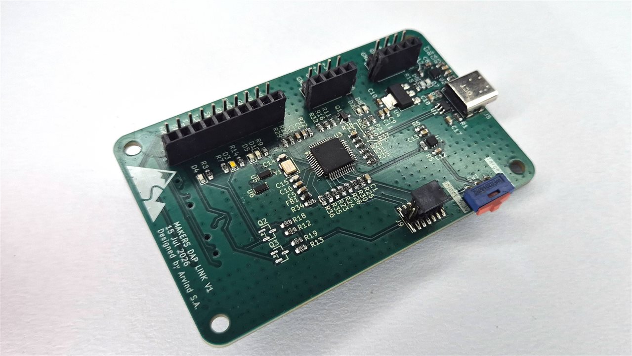
Mechanically, the board landed on a 50x90mm portrait shape, USB-C on top, connectors running down one long edge, 4-corner M3 mounting. After the Assembly it looked like this. Note how lined up the passives are around the STM32.
Final Notes
I Successfully manged to program, verify, extract firmwares on STM32, Nordic, MAX52632, and couple of other vendors too. The Programmer does show up as COM port, but it is not working. Argh, This is the problem with using Pre Compiled Firmwares Lazily. No Problem, I will flash a custom firmware to check if there is any error with the circuit before I blame the firmware. My Clients did love the Concept and the final design. Now, to make few of them and give it.