


Introduction
The idea behind this project was simple: build a small, physical timer from basic electronic components that could provide a tangible indication that a certain amount of time had passed. Rather than relying on a phone or software application, I wanted to understand and build the underlying electronics myself using concepts from digital and analog electronics.
The Problem: Losing Track of Time
I noticed that my mind gets distracted quite easily while trying to work, whether I am studying, reading, or doing something else that requires sustained attention. My mind would wander, and time could pass almost unnoticed until I realized that several hours had gone by.
After reading about the problem, I found that this can be a genuine challenge for neurodivergent people. One thing that seemed useful was having a physical object in the background that could continuously remind me of the passage of time.
A wristwatch or table clock is one obvious solution. Another is a visual kitchen timer. However, instead of simply buying one of these devices, I wanted to understand how such a device could be built from the fundamentals.
The Idea and Inspiration
I started thinking about a small electronic contraption that could both keep track of elapsed time and alert or interrupt me when a particular amount of time had passed.
My basic goal was to create a simple clock-like timer with an alarm, using as little power as possible so that it could eventually be made compact, portable, and battery-powered rather than requiring constant connection to a power source.
This led me to look at how wristwatches manage to keep time for months or years using tiny button cells. That introduced me to the concept of a quartz movement. A quartz crystal oscillator generates a very stable electrical oscillation, which is then divided down into regular pulses. Traditional quartz watches use these pulses to drive a stepper motor and gear train that move the second, minute, and hour hands.
The concept was fascinating, but recreating the entire mechanism mechanically would be far too complex and time-consuming for a simple DIY electronics project. Even if I managed to generate one pulse every second, using a mechanical gear train to keep track of minutes and hours would still be unnecessarily complicated.
However, I realized something important: at the fundamental level, keeping track of time requires a reasonably consistent source of periodic events or pulses. Instead of physically moving gears, those pulses can be counted electronically. If the pulses occur at a known interval, counting them allows us to measure elapsed time and trigger an event after a desired number of pulses.
That became the fundamental idea behind my project.
Parts Used
The main components used in the current prototype are:
- NE555 timer IC — pulse generation in astable mode
- CD4017BE decade counter — counting and dividing the generated pulses
- Resistors — setting the timing characteristics of the 555, 10K ohm and 220 ohms for leds
- Capacitor — setting the timing characteristics of the 555, 100uF
- LEDs — visual indication of counter output/timer state
- Zero PCB / perf board
- Headers and jumper wires — prototyping and testing
- 5V power source — Two lithium ion cells stepped down to 5v
- Jumper wires and header pins
From Digital Electronics to the Project Architecture
During my fifth semester of BTech CSE, I studied Digital Electronics and Logic Design, where I came across the 555 timer IC. One of its operating modes, the astable mode, can continuously generate a square-wave-like pulse signal. The frequency can be adjusted using resistors and a capacitor.
This gave me a way to generate the basic time reference for my project.
I also remembered another IC from digital electronics: the CD4017BE decade counter. It can sequentially activate ten decoded outputs, Q0 through Q9, in response to clock pulses supplied to its clock input.
So I decided to combine the two:
NE555 Timer → periodic pulses → CD4017 Decade Counter → elapsed-time output → LED/Buzzer
| {gallery}Circuit Diagrams |
|---|
|
|
|
|
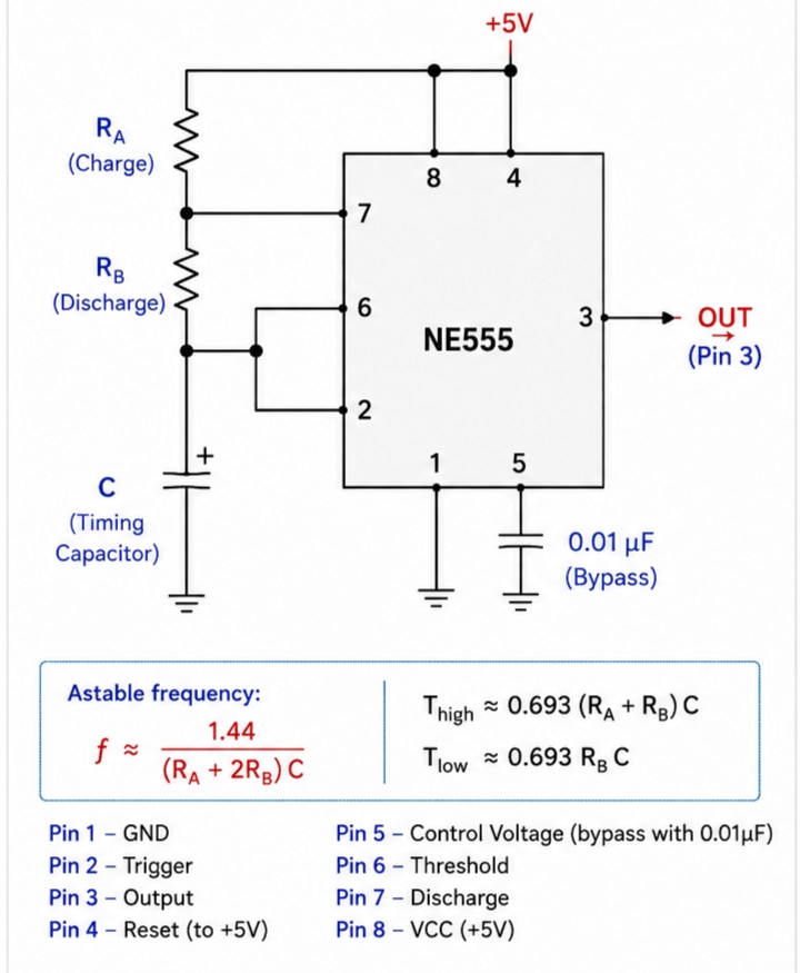
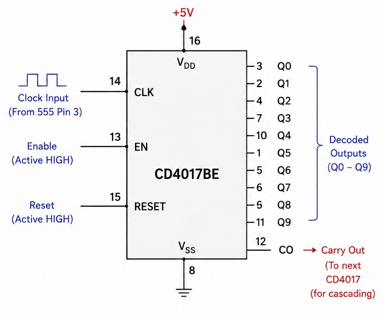
My initial architecture was therefore to generate a pulse as consistently as possible, ideally somewhere in the range of a few seconds per pulse, and then use the decade counter to count those pulses. By taking an output from one of the later counter stages, I could create a much longer delay than the individual 555 pulse period.
For example, if one pulse represented approximately 5 seconds, the tenth counted pulse would represent approximately 50 seconds. An LED or buzzer connected to an appropriate counter output could then act as the alert.
I knew there were much easier alternatives, such as timer applications and commercially available ergonomic timers. But that was not really the point of this project. What is the use of learning these concepts as an engineer if I never try to implement them myself?
I believe abstraction is extremely useful and convenient, but building things from fundamentals provides a different kind of understanding. Practical implementation is often where theoretical concepts become intuitive, and this is something I feel is easily missed in engineering education.
Initial Plan
At this stage, I thought the project would be relatively straightforward. My plan was essentially:
- Generate a consistent pulse using an NE555 in astable mode.
- Feed the pulse into a CD4017 decade counter.
- Use one of the later counter outputs to obtain a longer time interval.
- Connect an LED or buzzer to the selected output as an alert.
- Initially power the circuit through a 5V USB connection.
- Eventually make it portable by adding a suitable lithium-ion battery and power circuitry.
- Add a way to select different timer durations.
I initially ordered the decade counter along with components for my other electronics projects. I deliberately ordered only one CD4017, because I expected that I would be able to configure the 555 to produce a sufficiently long pulse period that a single decade counter would provide at least several minutes of timing.
That assumption turned out to be one of the first problems I encountered.
The First Major Problem: Getting a Long and Reliable Pulse
With the components I had available, I found that I could not reliably generate a pulse much longer than roughly 15 seconds using the NE555 configuration.
This meant that even with the CD4017 counting ten stages, the maximum practical timer duration was only around two minutes rather than the several minutes I had initially hoped for.
For example, if the 555 produced a pulse approximately every 12 seconds, reaching the tenth counter state would take approximately:
12 seconds × 10 ≈ 120 seconds
So the basic architecture worked, but the range of useful timing intervals was much smaller than I had expected.
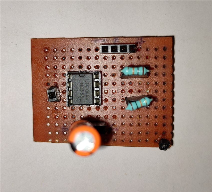
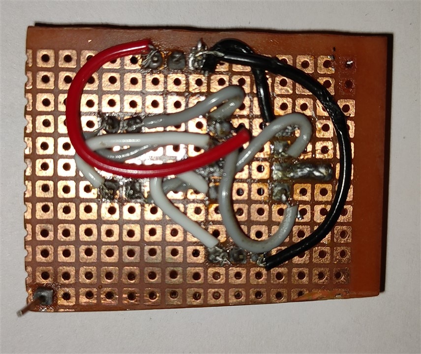
| {gallery}NE555 timer ic |
|---|
|
Front |
|
Back |
Attempting to Extend the Timer by Cascading Counters
The obvious solution was to increase the number of counting stages.
The CD4017 has a carry-out (CO) output that can be used to drive another counter, allowing multiple counters to be cascaded or daisy-chained. In principle, this would allow the first CD4017 to count ten pulses and then provide a signal that could advance a second counter.
This would dramatically increase the possible timing range without requiring the 555 itself to generate extremely long pulses.
Unfortunately, this introduced another practical problem: I only had one decade counter.
When I went to a local electronics store to find another one, I discovered how difficult it can be to find specific electronic components locally. Many of the stores in my area are primarily electrical stores rather than electronics component stores. I was eventually lucky enough to find a shop that actually stocked electronic components, although it did not have everything I was looking for.
I found suitable capacitors and resistors, but the CD4017 was unavailable. Instead, the shopkeeper gave me a CD4066BD, telling me that it was the same thing.
It was not.
After researching the component later, I found that the CD4066 is an analog switch IC, designed for switching analog or digital signals electronically. It is fundamentally different from a decade counter and cannot simply replace a CD4017 in this circuit.
That was an interesting reminder that identifying components correctly is just as important as knowing how to connect them.
| {gallery}CD 4017 Decade Counter |
|---|
|
Front |
|
Back |
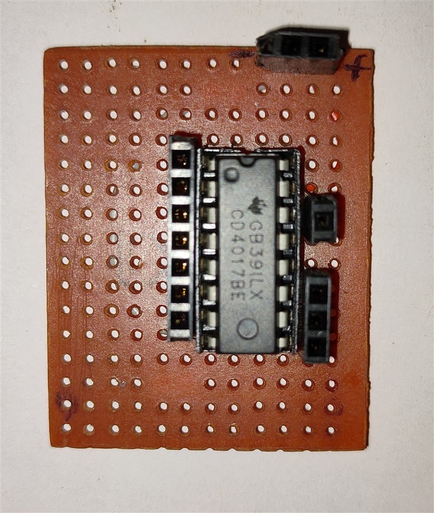
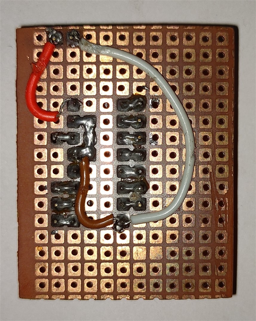
The Second Problem: Component Tolerances
Since I could not immediately obtain another CD4017, I decided to continue experimenting with the single counter and try to increase the 555's pulse period instead.
The problem is that increasing the timing resistance and capacitance introduces another challenge: component tolerances and non-ideal behavior become increasingly important.
The timing of an astable 555 circuit depends on its resistor and capacitor values. In an ideal calculation, changing these values gives a predictable change in frequency. In a real circuit, however, the actual values can differ from their nominal values because of component tolerance.
Capacitors can also have significant variation, leakage, temperature dependence, and other non-ideal characteristics. The resistors I had available also had limited value ranges and tolerances.
The capacitors I had were particularly unsuitable for accurately producing long delays. Some had poor or unspecified tolerances, and I did not have a sufficiently wide range of capacitor values to experiment systematically.
This made me realize that simply calculating a resistor-capacitor combination on paper is not enough when building a practical timer. The quality and tolerance of the actual components matter considerably.
As a result, I decided that getting a proper resistor and capacitor assortment kit would make further experimentation much easier.
Another Lesson from the NE555
I also noticed that the measured timing of my particular NE555 circuit did not always match the value predicted by the standard astable-mode equations.
Initially, I thought this might be because the particular NE555 I was using was a newer version of the traditional 555. However, I learned that the difference is better explained by the fact that the standard equations describe an idealized circuit, while real components have tolerances and non-ideal characteristics.
Factors such as the actual resistor and capacitor values, capacitor leakage, supply voltage, and the characteristics of the specific 555 implementation can all contribute to differences between the theoretical and measured timing.
This became another useful part of the project: the circuit was teaching me where theoretical equations stop being perfectly predictive and where real-world electronics begins.
Current State of the Prototype
At present, the project is still under development, but I have a working basic prototype.
I have soldered the ICs and the static parts of the circuit onto a zero PCB/perforated prototype board, along with the necessary headers. For power, testing, and experimentation, jumper wires are still heavily used.
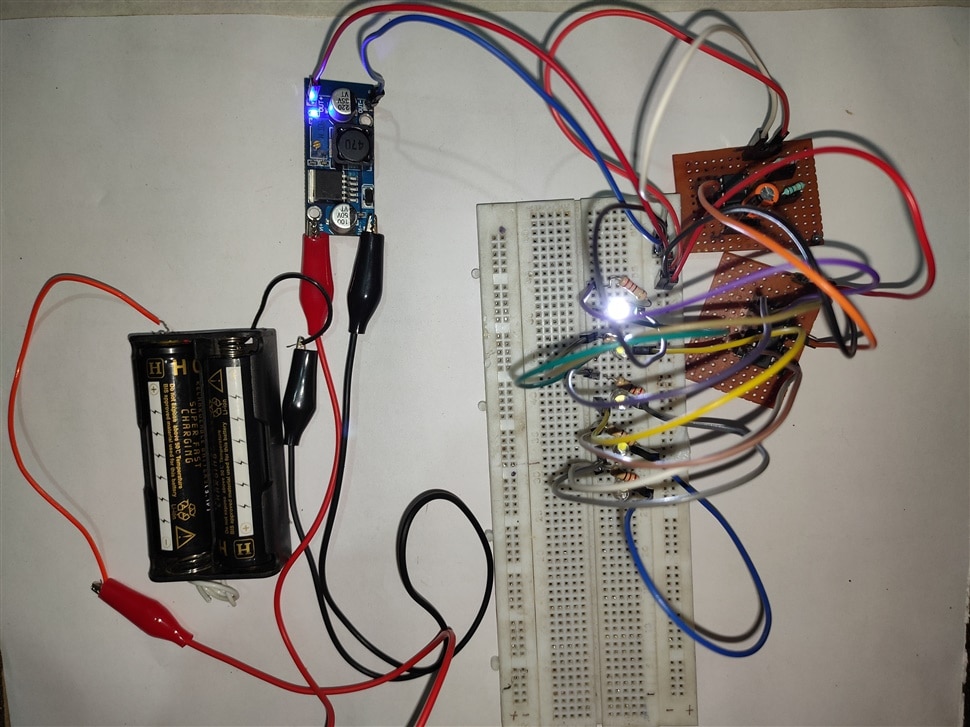
The basic concept of generating pulses with the NE555 and feeding them into the CD4017 is working. The remaining challenge is achieving a sufficiently long and, more importantly, sufficiently reliable timing interval for the final timer.
I have ordered a resistor and capacitor assortment so that I can experiment with a much wider range of component combinations. I also plan to obtain additional decade counters so that I can test cascading multiple CD4017 counters. I also plan to add a debounce switch to use the reset pin properly as its sensitive and sometimes triggers false increments.
What Remains
The next stage of the project has several goals.
First, I want to experiment with the new resistor and capacitor assortment to find combinations that provide longer and more consistent pulse intervals.
Second, I want to obtain additional CD4017 counters and experiment with cascading multiple counters. This should allow substantially longer timer durations without depending entirely on extremely long 555 timing intervals.
Once the timing behavior is satisfactory, I plan to make the prototype more self-contained by replacing the temporary wiring with a cleaner circuit layout.
I also intend to add a 5V USB Type-C input for convenient power and eventually investigate a suitable rechargeable lithium-ion battery arrangement to make the timer portable.
Finally, I want to add a simple pin selector or DIP-switch mechanism so that different counter stages can be selected as different timer durations. This would allow the same circuit to provide multiple preset time intervals rather than having to rebuild the circuit for every duration.
Conclusion and Progress
What started as a simple attempt to build a physical reminder of passing time has turned into a practical experiment in analog timing, digital counting, component tolerances, prototyping, and hardware troubleshooting.
The current prototype proves the basic concept: a 555 timer can provide the clock signal, and a decade counter can count those pulses to produce a longer time interval. However, achieving the reliability and range I originally wanted has proved more challenging than expected.
The project is therefore not finished yet, but the core prototype is operational. The next major milestones are improving timing accuracy, experimenting with better components, testing cascaded decade counters, and finally turning the experimental circuit into a compact and portable timer.
Thankyou for reading till the end. Eager to know you opinions on this project.