


This project details the hardware architecture, firmware mechanisms, and interface dynamics of an embedded electronic access control system (EACS) centered on the STM32-based Nucleo-L476RG platform. Featuring a dynamic matrix keypad scanner, a TM1637-driven 7-segment LED display module, and a Pulse-Width Modulation (PWM) controlled servomechanism, the system manages secure state transitions between locked and unlocked modes.
Embedded access control systems require a rigorous balance between input validation latency, user feedback precision, and physical actuator safety. Utilizing traditional microcontroller unit (MCU) peripherals without non-blocking structures often leads to UI freeze or missed keystrokes during prolonged execution loops (e.g., waiting for motor displacement).
This work addresses the realization of a deterministic, state-machine-driven door lock interface implemented on the STM32L476RG microcontroller (ARM® Cortex-4 core operating up to 80 MHz). The interface combines:
-
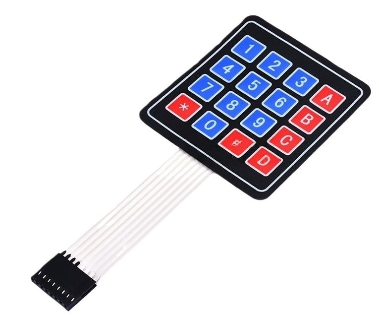
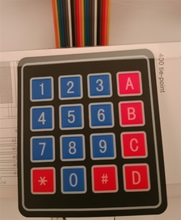
A 4×4 membrane keypad for credential entry and administrative triggers.
-
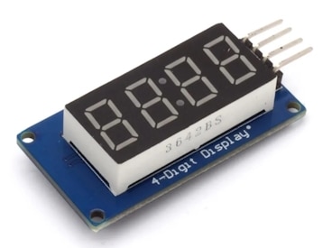
A TM1637 two-wire display controller for Human-Machine Interface (HMI) feedback.
-
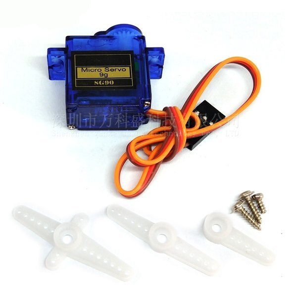
A high-torque positional servo motor for locking bolt engagement.
Hardware Architecture & Pin Topology
The system topology maps digital, analog, and power routing to isolate high-current inductive spikes generated by the motor from sensitive logic lines.
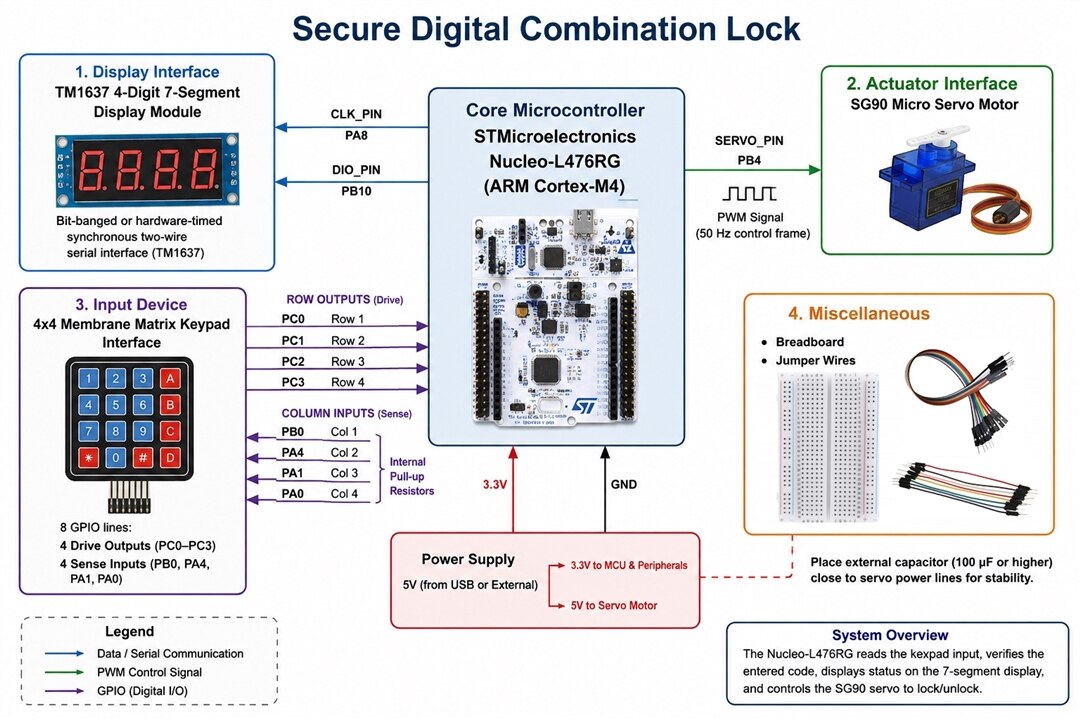
System Interconnect Topology
-
Core Microcontroller: STMicroelectronics Nucleo-L476RG (ARM Cortex-M4)
-
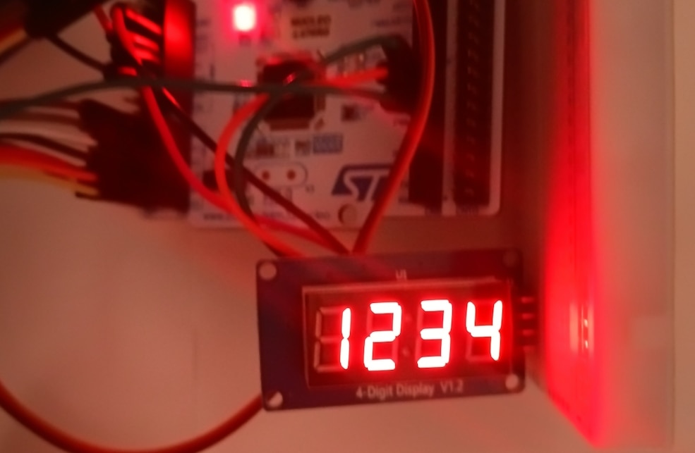
Display Interface (TM1637 4-Digit 7-Segment Display Module): Bit-banged or hardware-timed synchronous two-wire serial interface (
CLK_PINonPA8,DIO_PINonPB10). -
Actuator Interface: SG90 Micro Servo Motor - PWM channel driving a 50 Hz control frame (
SERVO_PINonPB4). -
Input Device: 4x4 Membrane Matrix Keypad Interface - 8 GPIO lines partitioned into 4 drive outputs (
PC0–PC3) and 4 sense inputs with internal pull-up resistors (PB0,PA4,PA1,PA0). -
Misc: Breadboard, jumper wires, external capacitor (recommended for servo decoupling)
Hardware Pinout Configuration
| Component | Signal / Function | Microcontroller Pin (Nucleo-L476RG) |
| Keypad Rows | Row 0–3 (Drive) | PC0, PC1, PC2, PC3 |
| Keypad Columns | Column 0–3 (Sense) | PB0, PA4, PA1, PA0 |
| TM1637 Display | CLK (Clock) | PA8 (Arduino D7) |
| TM1637 Display | DIO (Data) | PB10 (Arduino D6) |
| SG90 Servo | PWM Control | PB4 (Arduino D5) |

Key Technical Challenges Solved
-
Eliminating External Dependencies: By writing a native scanning algorithm using
INPUT_PULLUPand dynamic row output toggling, the build environment remains lean and immune to version conflicts. -
Matrix Transposition & Calibration: Physical membrane keypads often feature internal trace crossings that differ from standard layout assumptions. Using systematic mapping adjustments resolved coordinate inversions cleanly in software.
-
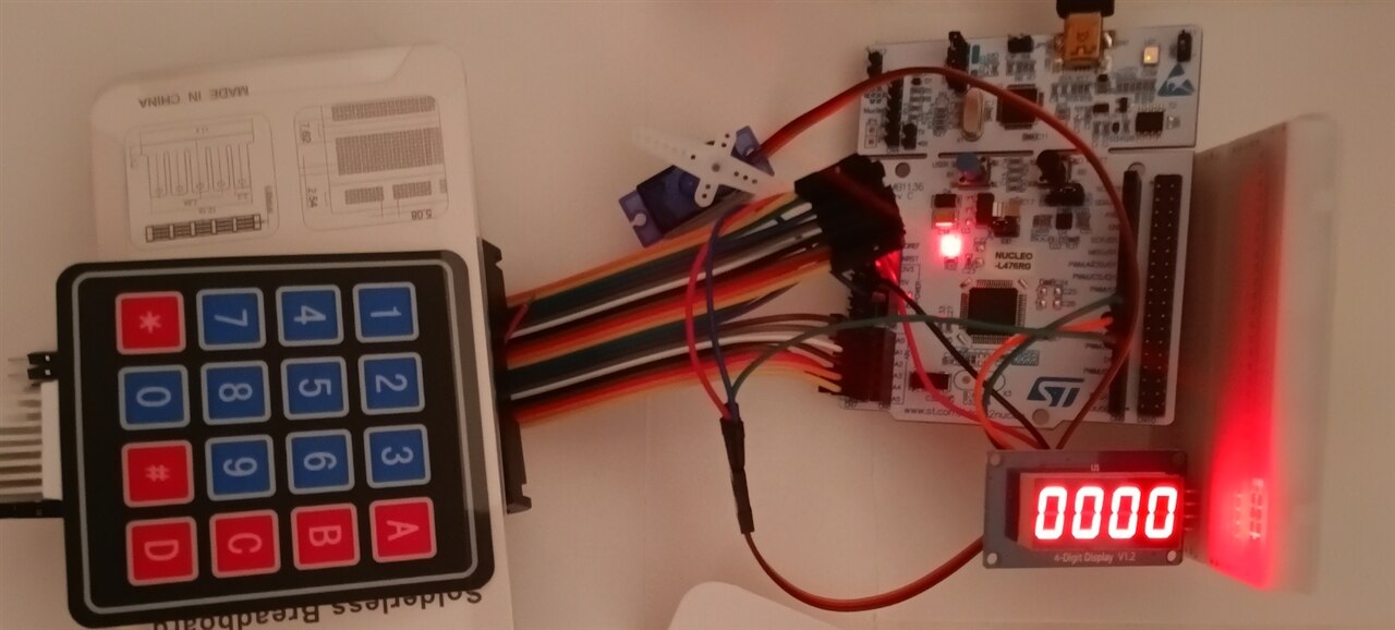
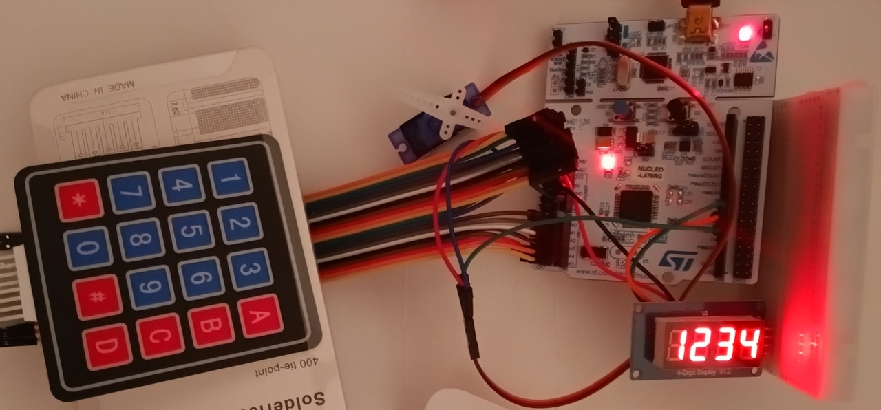
Non-Blocking UI State Machine: The system safely tracks entered PIN sequences against a hardcoded string (
"1234"), providing visual feedback via custom 7-segment glyphs (OPEn,CLO,Err) while supporting manual lockdown via key'A'.
Bill of Materials
-
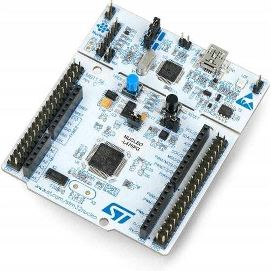
STMicroelectronics Nucleo-L476RG (ARM Cortex-M4)
-
4x4 Membrane Matrix Keypad
-
TM1637 4-Digit 7-Segment Display Module
-
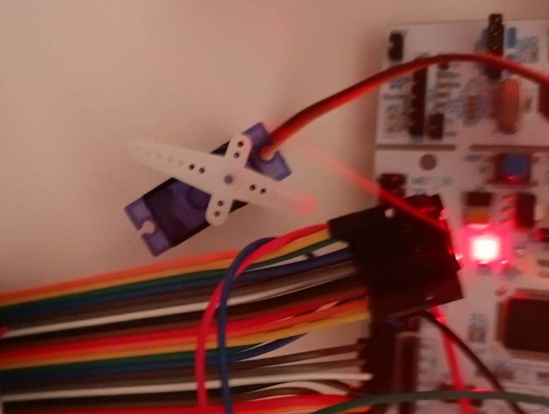
SG90 Micro Servo Motor
Complete Source Code
#include <Arduino.h>
#include <TM1637Display.h>
#include <Servo.h>

// --- DISPLAY AND SERVO PINS ---
#define CLK_PIN   PA8   // Pin D7 (Nucleo-L476RG)
#define DIO_PIN   PB10  // Pin D6 (Nucleo-L476RG)
#define SERVO_PIN PB4   // Pin D5 (Nucleo-L476RG)

// --- KEYPAD PIN MAPPING ---
const uint8_t rowPins[4] = {PC0, PC1, PC2, PC3};
const uint8_t colPins[4] = {PB0, PA4, PA1, PA0};

// Calibrated 4x4 key map matrix
const char keyMap[4][4] = {
  {'D', 'C', 'B', 'A'},
  {'#', '9', '6', '3'},
  {'0', '8', '5', '2'},
  {'*', '7', '4', '1'}
};

TM1637Display display(CLK_PIN, DIO_PIN);
Servo lockServo;

const String CORRECT_PIN = "1234";
String inputPin = "";

// 7-Segment Custom Glyphs
const uint8_t SEG_OPEN[] = {
  SEG_A | SEG_B | SEG_C | SEG_D | SEG_E | SEG_F, // O
  SEG_A | SEG_B | SEG_E | SEG_F | SEG_G,         // P
  SEG_A | SEG_D | SEG_E | SEG_F | SEG_G,         // E
  SEG_A | SEG_B | SEG_C | SEG_E | SEG_F          // N
};

const uint8_t SEG_CLOSE[] = {
  0x00,                                          // Blank
  SEG_A | SEG_D | SEG_E | SEG_F,                 // C
  SEG_E | SEG_F,                                 // L
  SEG_A | SEG_B | SEG_C | SEG_D | SEG_E | SEG_F  // O
};

const uint8_t SEG_ERR[] = {
  0x00,                                          // Blank
  SEG_A | SEG_D | SEG_E | SEG_F | SEG_G,         // E
  SEG_E | SEG_G,                                 // r
  SEG_E | SEG_G                                  // r
};

char readKeypad() {
  for (uint8_t r = 0; r < 4; r++) {
    pinMode(rowPins[r], OUTPUT);
    digitalWrite(rowPins[r], LOW);

    for (uint8_t c = 0; c < 4; c++) {
      if (digitalRead(colPins[c]) == LOW) {
        delay(40); // Soft debouncing
        while (digitalRead(colPins[c]) == LOW);

        pinMode(rowPins[r], INPUT_PULLUP);
        return keyMap[r][c];
      }
    }

    pinMode(rowPins[r], INPUT_PULLUP);
  }
  return 0;
}

void setup() {
  Serial.begin(115200);

  for (uint8_t i = 0; i < 4; i++) {
    pinMode(rowPins[i], INPUT_PULLUP);
    pinMode(colPins[i], INPUT_PULLUP);
  }

  display.setBrightness(0x0f, true);
  display.clear();
  display.showNumberDec(0, true);

  lockServo.attach(SERVO_PIN);
  lockServo.write(0); // Initial state: locked

  Serial.println("System ready. Use 'A' to lock manually.");
}

void loop() {
  char key = readKeypad();

  if (key != 0) {
    Serial.print("Pressed key: ");
    Serial.println(key);

    if (key == '#') { // PIN validation trigger
      if (inputPin == CORRECT_PIN) {
        Serial.println("Access granted. Lock opened.");
        display.setSegments(SEG_OPEN);
        lockServo.write(90); // Unlock position
      } else {
        Serial.println("Wrong code.");
        display.setSegments(SEG_ERR);
        delay(1500);
        display.clear();
        display.showNumberDec(0, true);
      }
      inputPin = "";
    }
    else if (key == 'A') { // Manual lock trigger
      Serial.println("Lock closed.");
      lockServo.write(0); // Lock position
      display.setSegments(SEG_CLOSE);
      delay(1500);
      inputPin = "";
      display.clear();
      display.showNumberDec(0, true);
    }
    else if (key == '*') { // Clear input buffer
      inputPin = "";
      display.clear();
      display.showNumberDec(0, true);
    }
    else if (key >= '0' && key <= '9') { // Digits entry
      if (inputPin.length() < 4) {
        inputPin += key;
        display.showNumberDec(inputPin.toInt(), false);
      }
    }
  }
}
Initialization and Pin Configuration
In this section, the hardware mapping is defined. The pins were chosen to avoid hardware conflicts (e.g., the external crystal oscillator on pins PH0/PH1). Keypad rows are controlled via port PC, and columns via PB and PA.
// --- DISPLAY AND SERVO PINS ---
#define CLK_PIN   PA8   // Pin D7 (Nucleo-L476RG)
#define DIO_PIN   PB10  // Pin D6 (Nucleo-L476RG)
#define SERVO_PIN PB4   // Pin D5 (Nucleo-L476RG)

// --- KEYPAD PINS ---
const uint8_t rowPins[4] = {PC0, PC1, PC2, PC3};
const uint8_t colPins[4] = {PB0, PA4, PA1, PA0};

// Calibrated key map matched to the physical ribbon cable layout
const char keyMap[4][4] = {
  {'D', 'C', 'B', 'A'},
  {'#', '9', '6', '3'},
  {'0', '8', '5', '2'},
  {'*', '7', '4', '1'}
};
Matrix Scanning Algorithm (Without External Libraries)
Instead of relying on unstable external PlatformIO libraries, the readKeypad() function implements fast, software-based row-scanning. Rows are cyclically pulled low (LOW), and columns are read using internal pull-up resistors (INPUT_PULLUP).
char readKeypad() {
  for (uint8_t r = 0; r < 4; r++) {
    // Activate the row by pulling it LOW
    pinMode(rowPins[r], OUTPUT);
    digitalWrite(rowPins[r], LOW);

    // Check columns for a short to ground (pressed key)
    for (uint8_t c = 0; c < 4; c++) {
      if (digitalRead(colPins[c]) == LOW) {
        delay(40); // Software debounce
        while (digitalRead(colPins[c]) == LOW); // Wait for key release

        pinMode(rowPins[r], INPUT_PULLUP); // Restore high-impedance state
        return keyMap[r][c]; // Return the corresponding character from the map
      }
    }

    pinMode(rowPins[r], INPUT_PULLUP);
  }
  return 0; // No active key
}
Seven-Segment Vector Graphics (Glyphs)
The TM1637 display does not have built-in support for letters, so we create custom bit arrays controlling individual segments (SEG_A through SEG_G) for messages such as OPEn, CLO (Close), and Err.
// Definition of the word "OPEn"
const uint8_t SEG_OPEN[] = {
  SEG_A | SEG_B | SEG_C | SEG_D | SEG_E | SEG_F, // O
  SEG_A | SEG_B | SEG_E | SEG_F | SEG_G,         // P
  SEG_A | SEG_D | SEG_E | SEG_F | SEG_G,         // E
  SEG_A | SEG_B | SEG_C | SEG_E | SEG_F          // N
};

// Definition of the word "CLO" (Closed)
const uint8_t SEG_CLOSE[] = {
  0x00,                                          // Space (segment turned off)
  SEG_A | SEG_D | SEG_E | SEG_F,                 // C
  SEG_E | SEG_F,                                 // L
  SEG_A | SEG_B | SEG_C | SEG_D | SEG_E | SEG_F  // O
};
Main Control Loop and State Machine
In the main loop, the program waits for a keypad event. Depending on the pressed key, the appropriate logic branch is executed:
-
Digit entry (
0-9): Appended to theinputPinbuffer (up to 4 characters) and rendered on the display. -
Confirmation (
#): Compares the entered string withCORRECT_PIN. On success, moves the servo to90°(unlock) and displaysOPEn. Otherwise, reports anErr. -
Manual closing (
A): Allows immediate locking (0°) and displays theCLOmessage. -
Reset (
*): Clears the input buffer.
void loop() {
  char key = readKeypad();

  if (key != 0) {
    if (key == '#') { // PIN verification
      if (inputPin == CORRECT_PIN) {
        display.setSegments(SEG_OPEN);
        lockServo.write(90); // Unlock mechanism
      } else {
        display.setSegments(SEG_ERR);
        delay(1500);
        display.clear();
        display.showNumberDec(0, true);
      }
      inputPin = "";
    }
    else if (key == 'A') { // Manual locking
      lockServo.write(0); // Lock mechanism
      display.setSegments(SEG_CLOSE);
      delay(1500);
      inputPin = "";
      display.clear();
      display.showNumberDec(0, true);
    }
    else if (key == '*') { // Clear inputs
      inputPin = "";
      display.clear();
      display.showNumberDec(0, true);
    }
    else if (key >= '0' && key <= '9') { // Accumulate PIN digits
      if (inputPin.length() < 4) {
        inputPin += key;
        display.showNumberDec(inputPin.toInt(), false);
      }
    }
  }
}
Developing secure, lightweight embedded applications often reveals that third-party library dependencies can introduce build system instabilities or bloated code. This project demonstrates how to build a fully functional electronic combination lock using an STM32 Nucleo-L476RG, an SG90 servo motor, a TM1637 4-digit display, and a standard 4x4 matrix keypad, relying entirely on native, non-blocking GPIO manipulation without external keypad libraries.