


Last week, while I was organizing my drawers, I found a Microchip AVR-IoT Cellular Mini developement board that I had used a couple of years ago to make the project of a control system to get alerts in case of fire or intrusions by burglars in my country house. When I had seen "Show and Tell" on Element14,I thought about making something using the AVR-IoT Cellular.
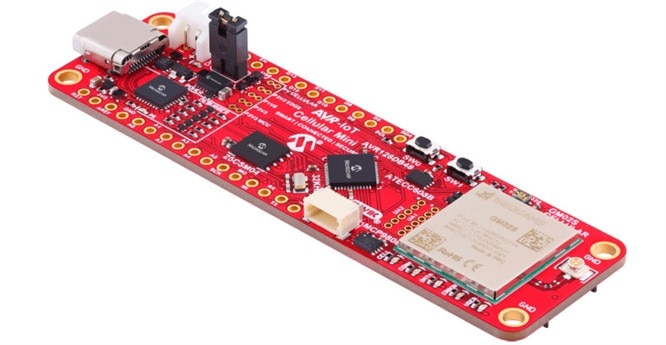 |
Microchip AVR-IoT Cellular Mini |
I thought about making something that my son has been asking me for a long time, a gate opener that avoids searching for keys in bags or backpacks and lets you open the house gate using your smartphone. The gate is far from the house, so using the home WiFi isn't a feasible solution. Cellular communication could be a good solution in this case.
I have used the MQTT protocol to make the board and my smartphone communicate.
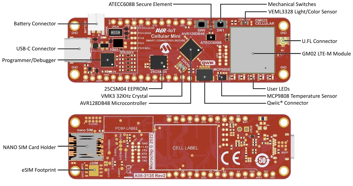
For those who have never used an AVR-IoT Cellular Mini, a great guide is the user guide. It fully describes the most important features of the board and explains in detail how to use it in the Arduino environment. Once the DxCore library is installed in the Arduino IDE, there will be plenty of code examples to start using the board. The project I want to create basically needs to wait for an event (an MQTT message coming from the smartphone) and then open the gate using a simple relay connected in parallel with the gate opener button.
I started my work by taking the example mqtt_custom_broker.ino as a model and modifying it so I could use it for my needs.
I used an MQTT server "test.mosquitto.org" that offers a convenient free service to test web applications that use MQTT. However, setting up a local MQTT server is very simple, and if I had had more time, it would have been more fun to set it all up on the Raspberry I use to manage some IoT devices in my home.
I used a 3V relay from Seeed to control the electric gate opener that runs on 12V.
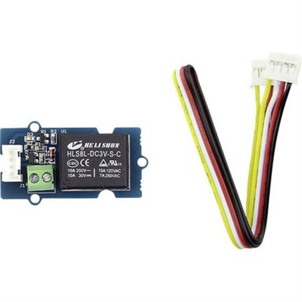 |
Seeed Switch Development Kit, General Purpose MCU, MPU, DSP, DSC, Grove Starter Kit |
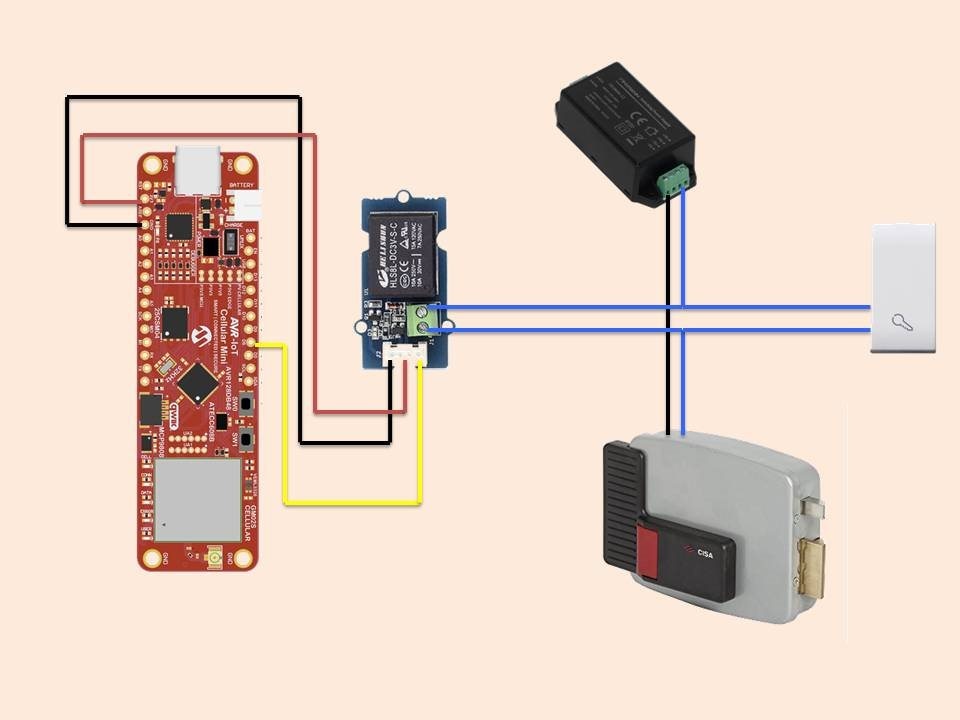
The code I wrote uses the public MQTT server I mentioned above and doesn't use any authentication or communication encryption. Obviously, this is fine for a simple test, but it needs to be considered if you want to create a project to use in real life.
/**
 * This code is based on mqtt_custom_broker.ino example .
 */

#include <Arduino.h>
#include <ecc608.h>
#include <led_ctrl.h>
#include <log.h>
#include <lte.h>
#include <mqtt_client.h>

// define MQTT parameters
#define MQTT_SUB_TOPIC "cancello"
#define MQTT_PUB_TOPIC "cancello"
#define MQTT_THING_NAME "gestione_casa"
#define MQTT_BROKER     "test.mosquitto.org"
#define MQTT_PORT       1883
#define MQTT_USE_TLS    false
#define MQTT_USE_ECC    false
#define MQTT_KEEPALIVE  60

// define Rele
#define RELE_PIN PIN_PE1  //PIN_PE1 is Arduino's D6

void setup() {
    Log.begin(115200);
    LedCtrl.begin();
    LedCtrl.startupCycle();
    pinMode(RELE_PIN, OUTPUT);
    digitalWrite(RELE_PIN, LOW);   //rele off
    Log.info(F("Starting MQTT with custom broker"));
    // Establish LTE connection
    if (!Lte.begin()) {
        Log.error(F("Failed to connect to operator"));
        // Halt here
        while (1) {}
    }

    // Attempt to connect to the broker
    if (MqttClient.begin(MQTT_THING_NAME,
                         MQTT_BROKER,
                         MQTT_PORT,
                         MQTT_USE_TLS,
                         MQTT_KEEPALIVE,
                         MQTT_USE_ECC)) {
        MqttClient.subscribe(MQTT_SUB_TOPIC);
    } else {
        Log.rawf(F("\r\n"));
        Log.error(F("Failed to connect to broker"));
        // Halt here
        while (1) {}
    }
}

void loop() {
    String message = MqttClient.readMessage(MQTT_SUB_TOPIC);
    // Read message will return an empty string if there were no new
    // messages, so anything other than that means that there was a new
    // message
    if (message != "") {
        Log.infof(F("Got new message: %s\r\n"), message.c_str());
        message.trim();   // elimina spazi, \n, \r
            if (mess.equals("Apri")) {
                Log.infof(F("UNO\r\n"));
                digitalWrite(RELE_PIN, HIGH); //rele on for 0.5 seconds
                delay(500);
                Log.infof(F("DUE\r\n"));
                digitalWrite(RELE_PIN, LOW);  // rele off
                }
        }
    delay(3000);
}
For managing the gate opening command from my smartphone, I used the MQTT Dashboard Client app. The setup is straightforward and everything worked on the first try. The interface is a bit bare, but I have to admit I didn't spend much time trying to fix this issue. It works perfectly and I didn't experience any malfunctions.

Possible future improvements:
- the board comes with a 2-pin connector that lets you connect a battery and the circuitry needed to charge the battery via the USB port. Due to time constraints, since the post deadline is very close, I decided to power the circuit with mains voltage and a simple USB-C power supply. It would be interesting to make an autonomous system using a solar panel, a charge controller an a battery.
- you have to use a strong authentication to protect the communication.

