


Introduction
This project is the development of a custom flight controller PCB built around the STM32F405RGT6 microcontroller.
My main goal is to gain hands-on experience in designing a complete embedded hardware platform from the schematic level to PCB implementation rather than relying on an existing commercial flight controller.
The board is being designed in Altium Designer and integrates the main sensing, communication, control, power-management, and debugging functions required for a small UAV-oriented embedded control platform.
The project is currently a work in progress. The schematic architecture and PCB component placement have been developed, while design verification, routing refinement, fabrication, firmware development, and hardware testing are the next stages.

1. System Architecture
The STM32F405RGT6 acts as the central processing unit of the board.
The hardware architecture includes:
• STM32F405RGT6 ARM Cortex-M4 microcontroller
• MPU-9250 inertial measurement unit
• BMP280 temperature and pressure sensor
• 25LC1024 SPI EEPROM
• GPS interface
• Telemetry interface
• User UART interface
• User I2C interface
• Four ESC control outputs
• Four servo outputs
• USB Type-C interface
• SWD programming and debugging interface
• Status LEDs and buzzer
• Dedicated 5 V and 3.3 V power rails
Several communication peripherals are used so that individual devices can be separated according to their requirements.
The design uses I2C, SPI, UART, USB, GPIO, interrupts, and timer/PWM channels.
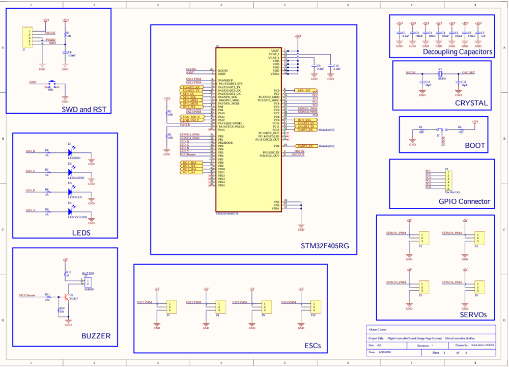
2. Microcontroller and Control Section
The main controller is the STM32F405RGT6.
I selected this MCU because it provides a Cortex-M4 core together with a large number of timers and communication peripherals, which makes it suitable for a flight-control-oriented embedded platform.
The microcontroller section includes:
• SWD programming and debugging
• Hardware reset
• BOOT configuration
• External 8 MHz crystal
• Local decoupling capacitors
• Four status LEDs
• Buzzer control
• ESC PWM outputs
• Servo PWM outputs
• Additional GPIO breakout connections
Special attention was given to providing decoupling capacitors around the MCU supply pins and making the major interfaces individually accessible during future debugging and firmware development.
3. Sensor and Communication Interfaces
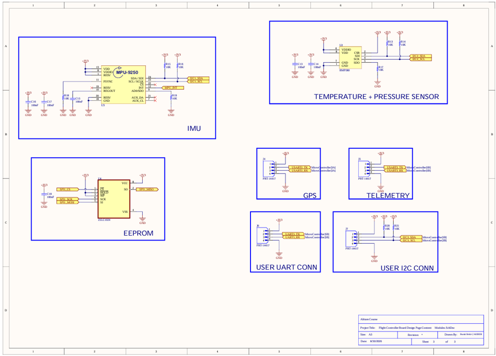
The board contains two main onboard sensors.
The MPU-9250 is used as the inertial measurement unit and provides motion-related measurements required by a flight-control system. It is connected to the STM32 through I2C and also provides an interrupt signal.
A BMP280 is included for pressure and temperature measurement and is connected through a separate I2C bus.
Using separate I2C buses allows the sensor interfaces to be organized independently and gives additional flexibility during firmware development and debugging.
A 25LC1024 EEPROM is connected through SPI for non-volatile storage.
The board also provides dedicated connectors for:
• GPS over UART
• Telemetry over UART
• Additional user UART
• Additional user I2C
This allows external modules to be added without redesigning the controller board.
4. ESC and Servo Control
Four dedicated ESC outputs are included in the design.
Each ESC connector provides:
• PWM control signal
• 5 V
• Ground
The STM32 timer peripherals are intended to generate the control signals.
Four additional servo outputs are also included, providing extra PWM channels for future actuators or auxiliary control mechanisms.
These interfaces were separated and clearly labeled to simplify wiring and debugging during future hardware testing.
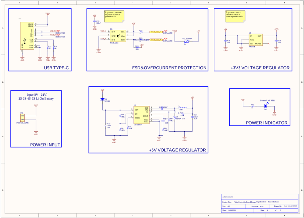
5. Power Architecture
The board can be powered from an external Li-ion battery source.
The present design targets an input range of approximately 8 V to 24 V.
An MP1584EN buck converter generates the 5 V rail from the main battery input.
The 5 V rail is then used directly by appropriate peripherals and is also supplied to an NCP718 linear regulator to generate the 3.3 V rail required by the STM32 and low-voltage peripherals.
The power section therefore follows:
Battery Input
→ MP1584EN Buck Converter
→ 5 V Rail
→ NCP718 LDO
→ 3.3 V Rail
The board also includes a power indicator LED.
USB Type-C is included for communication and development purposes.
The USB section contains:
• USB Type-C connector
• 5.1 kΩ configuration resistors
• USBLC6-2 ESD protection
• 22 Ω series resistors on the USB data lines
• Resettable overcurrent protection
Protection and filtering components were included around the USB and power interfaces to improve robustness during development.
6. PCB Design
After completing the main schematic architecture, I transferred the design to the PCB environment in Altium Designer.
The component placement was organized around the functional blocks of the system.
The STM32 is located near the central region of the board, while the major connectors are positioned near the PCB edges to make external wiring easier.
The USB Type-C interface is placed along the upper edge.
ESC and servo connections are placed around the sides of the PCB, while the power-input section is located toward the lower part of the board.
Sensors and supporting passive components were positioned near the MCU while considering signal length, accessibility, and future routing requirements.
The current PCB layout is still under development and will be refined before fabrication.
7. Current Development Status
Completed or substantially developed:
• Overall system architecture
• Main component selection
• STM32 peripheral assignment
• Power architecture
• USB Type-C interface
• Sensor interfaces
• GPS and telemetry connections
• EEPROM interface
• ESC and servo interfaces
• SWD and reset circuitry
• Schematic capture in Altium Designer
• PCB component placement
• Initial 3D PCB review
Still in progress:
• Final PCB routing
• Ground and power distribution refinement
• ERC and DRC verification
• Final footprint verification
• Design review
• Fabrication preparation
• PCB manufacturing
• Assembly
• Hardware bring-up
• STM32 firmware
• Sensor drivers
• Sensor calibration
• ESC output testing
• Flight-control software and testing
8. Engineering Challenges and Design Decisions
One of the main challenges in this project has been organizing a relatively large number of peripherals around a single microcontroller.
The board requires several simultaneous communication interfaces, including I2C, SPI, UART, USB, GPIO, interrupts, and PWM outputs.
For this reason, peripheral and pin allocation was an important part of the schematic design.
Power distribution was another important consideration because the board contains both 5 V and 3.3 V domains while being supplied from a considerably higher battery voltage.
The PCB layout also requires balancing several competing requirements:
• Keeping decoupling components close to their ICs
• Minimizing sensitive sensor signal lengths
• Providing convenient access to external connectors
• Organizing PWM and communication interfaces
• Maintaining appropriate power and ground paths
• Keeping the board practical for debugging and assembly
These considerations are still being evaluated as the PCB progresses toward its final revision.
9. Next Steps
My next steps for the project are:
1. Complete and optimize the PCB routing
2. Review power and ground distribution
3. Run final ERC and DRC checks
4. Verify every footprint against the component datasheet
5. Generate manufacturing files
6. Fabricate the PCB
7. Assemble and perform initial power-up tests
8. Verify the 5 V and 3.3 V rails
9. Bring up the STM32 through SWD
10. Develop and test the sensor interfaces
11. Test GPS, telemetry, ESC, and servo outputs
12. Begin flight-control firmware development
Since this is still an active project, I plan to continue documenting the design, fabrication, bring-up, and testing stages as the hardware progresses.
Thank you for reading!